Die-cutting machine for printing

A die-cutting machine, hot stamping machine technology, applied in printing machines, rotary printing machines, printing, etc., can solve the problems of messy tearing of paper burrs, labor-intensive, blurred printing surface, etc., to improve processing efficiency and Pass rate, improve smoothness and uniformity, and improve the effect of underwriting

Inactive Publication Date: 2020-12-15
余清河
View PDF0 Cites 0 Cited by
  • Summary
  • Abstract
  • Description
  • Claims
  • Application Information

AI Technical Summary

Problems solved by technology

[0004] Aiming at the deficiencies in the prior art, the purpose of the present invention is to provide a die-cutting machine for printing, to solve the problem that the paper pulp layer of the printing paper will produce stamped paper scraps and burrs during printing. It will cause messy tearing of the paper scraps and burrs on the edge of the printing paper, which will lead to the blurring of the printing surface af

Method used


Image

  • Die-cutting machine for printing
  • Die-cutting machine for printing
  • Die-cutting machine for printing

Examples


Embodiment 1

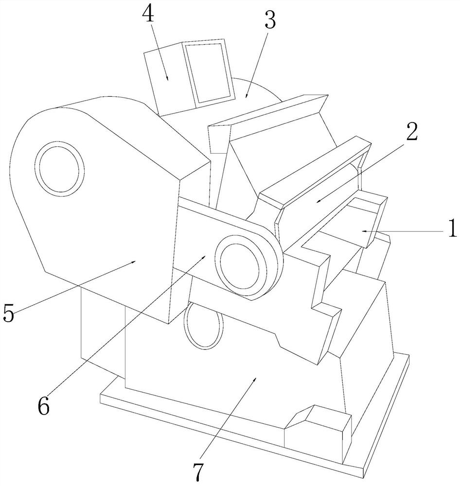
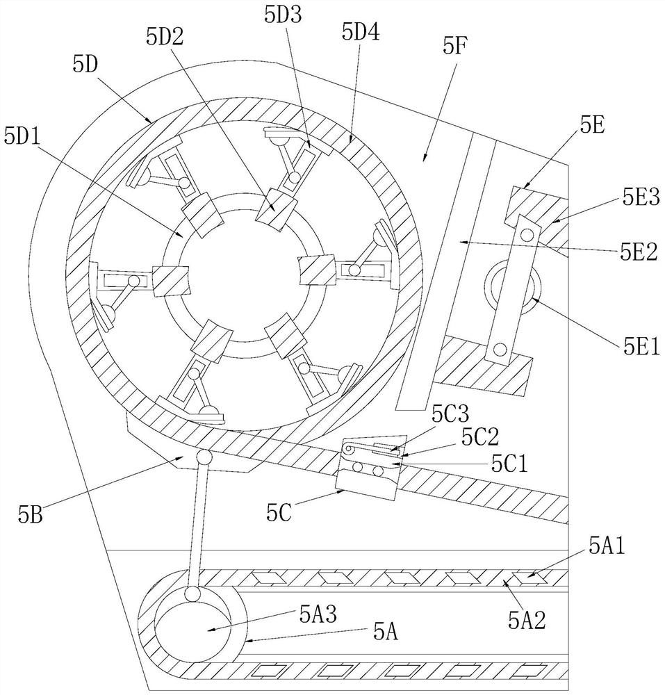
[0033] see Figure 1-Figure 6, the present invention provides a die-cutting machine for printing, its structure includes: a die-cutting guillotine table 1, a continuous supply roller 2, a printing drum 3, a distribution box 4, a stamping film frame 5, a conveyor belt 6, The base column block 7, the stamping film frame 5 is nested on the front side of the printing drum 3 and the axes are collinear, the distribution box 4 is installed on the top of the printing drum 3, and the connecting The supply roller 2 is mechanically connected to the printing drum 3 through the conveyor belt 6, the conveyor belt 6 is inserted on the right side of the stamping film frame 5 and is on the same vertical plane, and the die-cutting guillotine table 1 is nested in the On the top of the base column block 7, the continuous supply roller 2 is installed on the top of the die-cutting guillotine platform 1, and the stamping film frame 5 is provided with a fin conveyor belt 5A, a roller support bar 5B, ...

Embodiment 2

[0040] see Figure 1-Figure 6 , the present invention provides a kind of die-cutting machine for printing, other respects are identical with embodiment 1, and difference is:

[0041] see figure 2 , the hinged support wheel frame 5E is composed of a hinged wheel body 5E1, an inclined frame liner 5E2, and a folding frame support plate seat 5E3. On the same vertical plane, the folded frame support plate seat 5E3 is installed on the right side of the inclined frame liner plate 5E2, and the folding frame support plate seat 5E3 is pressed and covered by the sloped frame liner plate 5E2 to form the effect of protecting the printing cylinder on the side. , and adapt to the overall disk wheel to form the effect of carding around the paper surface.

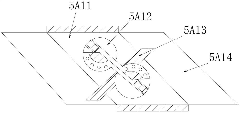
[0042] see Figure 6 , the hinged wheel body 5E1 is composed of a wheel frame ring 5E11, a wing support plate 5E12, a three-lobe wheel core 5E13, and a brush pole block 5E14, and the three-lobe wheel core 5E13 is installed inside the wh...


PUM


Abstract

The invention discloses a die-cutting machine for printing. The die-cutting machine structurally comprises a die-cutting guillotine table, a continuous supply roller, a printing rotary cylinder, a distribution box, a heat-stamping and film-drawing machine frame, a conveyor belt and a base column block. The heat-stamping and film-drawing machine frame is used to be matched with the conveyor belt, the continuous supply roller is driven by the conveyor belt to be matched with a heat-stamping roller combing plate to press the printing rotary cylinder in a surrounding mode, after a printing surfacepretreated by an outer disc ring of a top-layer chain belt forms hot roller transferring, paper scraps and burrs are carded through a paper carding supporting cushion frame to achieve the effect of one-direction orientation of the paper scraps and burrs, then at the bottom end, a sliding shuttle thin film pulling and covering effect is achieved through a film pulling sliding block, the overall die cutting film surface smoothness and uniformity are improved, the situation that a tightening one-time-cutting effect is formed due to the fact that paper pulp inner-layer burrs are interfered and torn is avoided, a chain belt type sliding frame is matched to form the effect of wheel lead linkage line spacing transmission middle section pretreatment to protect a printing paper surface, so that the later rework condition is avoided, the flatness of the printing surface and a die cutting edge is improved, the insufficient receiving of an all-in-one machine is improved, and the continuous machining efficiency and the percent of pass are improved.

Description

technical field [0001] The invention relates to a die-cutting machine for printing, which belongs to the field of printing. Background technique [0002] The integrated processing of the printing machine and the die-cutting machine will form a large-scale continuous processing operation effect of the top roller brush and the bottom slide knife die-cutting, improve the sluggishness of the pipeline due to insufficient printing volume of the project, and ensure the printing and die-cutting linkage of the all-in-one machine. To increase the workload of the factory and reduce the floor space, the shortcomings of the current technology to be optimized are: [0003] The pulp layer of the printing paper will produce stamped paper burrs during printing. After continuous feeding operation, die-cutting and paper separation, the paper burrs on the edge of the printing paper will be messy and torn, resulting in micro fluff on the printing surface after die-cutting. The printing surface ...

Claims


Application Information

Patent Timeline
IPC IPC(8): B41F19/00
CPCB41F19/008
Inventor 余清河
Owner 余清河
Why Eureka
Try Eureka