Three-symmetric-point hydraulic rolling head

A rolling head and rolling technology, applied in the direction of fluid pressure actuation device, etc., can solve problems such as heavy wear, and achieve the effects of improving mechanical properties, improving surface grain refinement, and simple manufacturing process

Inactive Publication Date: 2020-12-15
JIANGLU MACHINERY & ELECTRONICS GROUP
View PDF6 Cites 2 Cited by
  • Summary
  • Abstract
  • Description
  • Claims
  • Application Information

AI Technical Summary

Problems solved by technology

like figure 2 The pressure head structure, the high-pressure oil enters the high-pressure oil chamber through the oil inlet, and under the action of the high-pressure oil, the piston is pushed to move to the surface of the rolling product (when the high-pressure oil is reduced to negative pressure, the atmospheric pressure pushes the piston to shrink and move), and the support roller moves the piston The pressure is transmitted to the steel ball, so that the steel ball contacts the surface of the product for rolling. The support roller directly contacts the steel ball and rotates to transmit the pressure. The wear between the two is heavy, which often causes the support roller and the steel ball to be worn and replaced.

Method used


Image

  • Three-symmetric-point hydraulic rolling head
  • Three-symmetric-point hydraulic rolling head
  • Three-symmetric-point hydraulic rolling head

Examples


Embodiment 1

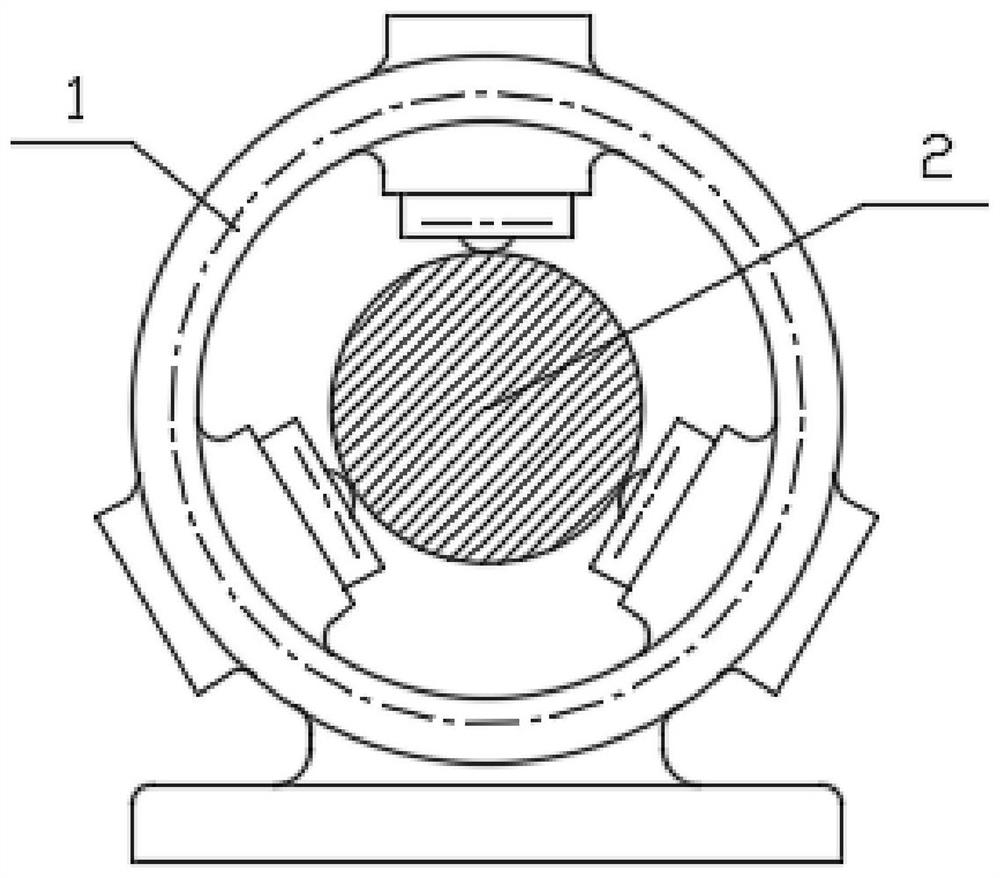
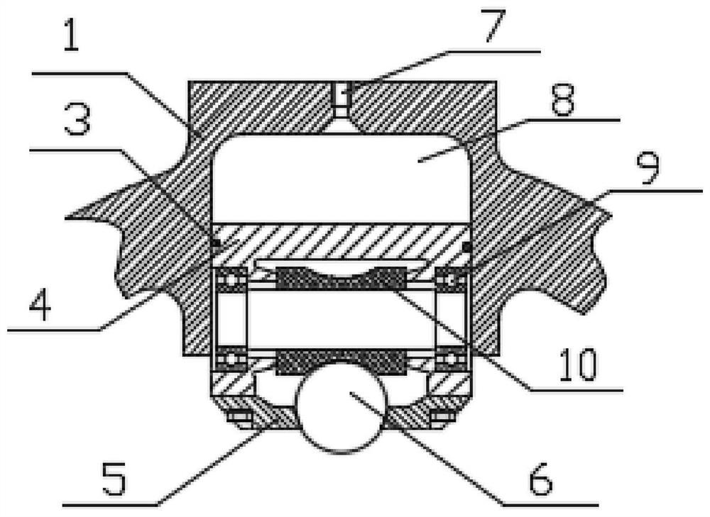
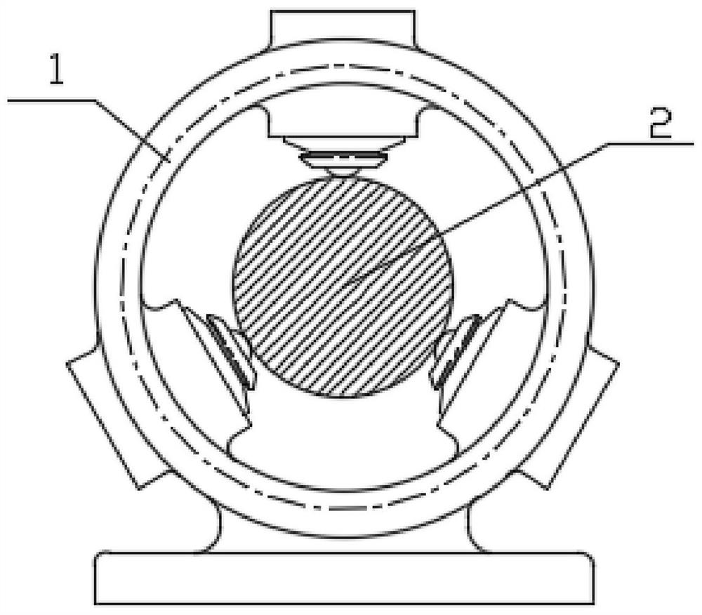
[0026] The three-symmetric point hydraulic rolling head provided by the preferred embodiment of the present invention, the three-symmetric point hydraulic rolling head includes a support seat 1 and a rolling product 2, and three rolling steel balls 6 are arranged on the support seat 1 , evenly distributed on the outer circle of the rolling product 2, and the resultant force is zero; the oil inlet 7 is set on the support seat 1, and the high-pressure oil chamber 8 is formed between the oil inlet 7 and the rolling steel ball 6, and the high-pressure oil chamber 8 The piston 4 is arranged near the rolling steel ball 6, and the piston 4 and the rolling steel ball 6 are closely attached to the outside of the steel ball, and a φ0.15~φ0.30 through hole is drilled in the center of the pressing axis of the piston 4.

[0027] When working: Compared with the traditional design, this scheme abandons the way that the single-row ball bearing 9 and the support roller 10 are in direct contact ...

Embodiment 2

[0029] On the basis of the first embodiment, this embodiment further includes a support cover 5 arranged at the bottom of the piston 4 . The sealing ring 3 is arranged between the piston 4 and the support seat 1 .

[0030] When working: Due to the leakage of hydraulic oil between the steel ball and the spherical surface of the integral piston, it is necessary to control the pressure value of the steel ball. The spherical precision of the high-precision steel ball and the piston must be selected to control the gap between the two spherical surfaces at 0.015-0.02mm. At the same time, the hydraulic oil needs to be greater than 15-20Mpa.


PUM

PropertyMeasurementUnit
hardnessaaaaaaaaaa

Abstract

The invention discloses a three-symmetric-point hydraulic rolling head, and the three-symmetric-point hydraulic rolling head is suitable for surface hardening and roll finishing of ferrous metal or nonferrous metal with high hardness so as to improve the surface grain refinement degree, corrosion resistance, abrasion resistance and fatigue resistance of ferrous metal or nonferrous metal parts. Themechanical performance of components can be improved on the premise that materials, weight and hardness are not changed. The three-symmetric-point hydraulic rolling head aims to solve the problems that an existing rolling auxiliary tool adopts mechanical three-point uniform distribution hard contact, steel ball abrasion is large, and the rolling cost is very high. By changing the pressing head structure of the rolling auxiliary tool, three rolling heads are uniformly distributed and pressed on the outer circle of a product for rolling, the resultant force is zero, the product is in a balancedstate, and at the moment, an oil film can be formed between a steel ball and the surface of the product. The piston manufacturing process is relatively simple, an integrated piston is adopted for pressing the steel ball to replace an original supporting roller to transmit the pressure of the piston to the steel ball, the steel ball is in contact with the surface of the product for rolling, the supporting roller is in direct contact with the steel ball and rotates to transmit pressure, and only a supporting cover is used for fixing the steel ball to keep the steel ball fixed.

Description

technical field [0001] The invention belongs to the field of special crawler vehicles and relates to a hydraulic rolling head with three symmetrical points. Background technique [0002] During the driving process of special tracked vehicles, due to the rough road surface, the supporting balance elbows of the wheel hubs on both sides must maintain a symmetrical balance, otherwise the vehicle rollover accident will occur. The key component that supports this symmetrical balance on both sides is a slender rod spring—the torsion shaft. The torsion shaft is a high-hardness (45-50HRC) alloy steel with high elastic distortion and recovery capabilities. However, under the action of this alternating stress, the fine lines on the surface will transform into microcracks and expand into fracture cracks, which will eventually cause the torsion shaft to break, and the vehicle will not be able to drive. The solution to this problem is to carry out rolling surface hardening on the shaft o...

Claims


Application Information

Patent Timeline
Patent Type & Authority Applications(China)
IPC IPC(8): C21D7/04F15B15/14
CPCC21D7/04F15B15/1447
Inventor 成钢刘子聪袁剑平阳仁奇
Owner JIANGLU MACHINERY & ELECTRONICS GROUP
Why Eureka
Try Eureka