HiPIMS system and method for reducing HiPIMS discharge current delay
A discharge current and power supply technology, applied in the field of magnetron sputtering equipment, can solve the problems of intensifying gas atomic dilution effect, increasing the production cost of power supply, uncontrollable negative effects, etc., achieving rapid HiPIMS gas breakdown discharge and suppressing arc discharge produce, low-cost effect
- Summary
- Abstract
- Description
- Claims
- Application Information
AI Technical Summary
Problems solved by technology
Method used
Image
Examples
example 1
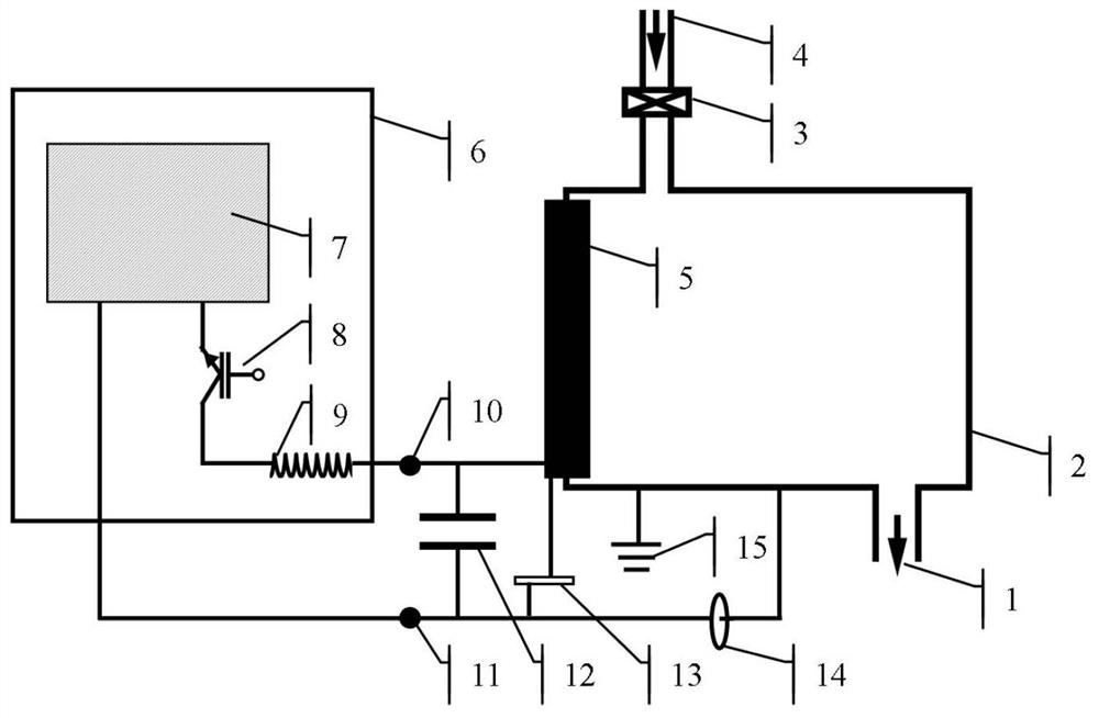
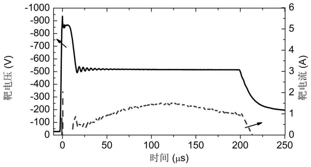
[0044] figure 2 When the power supply inductance is 50μH and the capacitive reactance of the selected capacitor is 22.5nF, at the output terminal of the power supply -500V, the waveform diagram of the target voltage and target current under the condition that the maximum oscillation voltage is -800V. When the gas is not broken down, the voltage can be maintained at -800V until the gas is broken down. Discharge conditions: the gas is argon at 0.5Pa, the target material is Cr target, the pulse width is 200μs, and the pulse frequency is 50Hz.
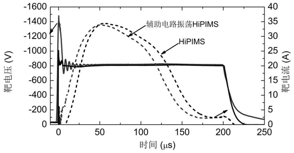
[0045] image 3 It is ordinary HiPIMS discharge and auxiliary circuit oscillating HiPIMS discharge, when the power supply inductance is 50μH, and the capacitive reactance of the selected capacitor is 22.5nF, the waveform diagram of the target voltage and target current under the condition of -800V at the output terminal of the power supply. Discharge conditions: the gas is argon at 0.5Pa, the target material is Cr target, the pulse widt...
example 2
[0055] Figure 4 It is a graph of the relationship between the current delay time and the output terminal voltage of the power supply (that is, the target voltage when the voltage is stable) in different discharge modes. The figure contains ordinary HiPIMS, with auxiliary circuit oscillating HiPIMS, whose capacitance values are 22.5nF, 55nF, 110nF and 220nF respectively. Discharge conditions: the gas is argon at 0.5Pa, the target material is Cr target, the pulse width is 200μs, and the pulse frequency is 50Hz.
[0056] see Figure 4 , the scheme of example 2 replaces the capacitor 22.5nF in the scheme of example 1 with 55nF, the relationship between the current delay time and the voltage is as follows Figure 4 As shown, other steps are the same as Example 1.
example 3
[0058] see Figure 4 , the scheme of example 3 replaces the capacitor 22.5nF in the scheme of example 1 with 110nF, the relationship between the current delay time and the voltage is as follows Figure 4 As shown, other steps are the same as Example 1.
PUM
 Abstract
Description
Claims
Application Information
 - R&D
- Intellectual Property
- Life Sciences
- Materials
- Tech Scout
- Unparalleled Data Quality
- Higher Quality Content
- 60% Fewer Hallucinations
Browse by: Latest US Patents, China's latest patents, Technical Efficacy Thesaurus, Application Domain, Technology Topic, Popular Technical Reports.
© 2025 PatSnap. All rights reserved.Legal|Privacy policy|Modern Slavery Act Transparency Statement|Sitemap|About US| Contact US: help@patsnap.com


