
Hipims system and method for reducing hipims discharge current delay

A discharge current and power supply technology, applied in the field of magnetron sputtering equipment, can solve the problems of intensifying gas atomic dilution effect, increasing the production cost of power supply, uncontrollable negative effects, etc., achieving rapid HiPIMS gas breakdown discharge and suppressing arc discharge produce, low-cost effect

Active Publication Date: 2022-05-10
BEIHANG UNIV
View PDF0 Cites 0 Cited by
  • Summary
  • Abstract
  • Description
  • Claims
  • Application Information

AI Technical Summary

Problems solved by technology

However, the disadvantages of this method are: the higher average discharge power puts forward higher requirements for target cooling, which will increase the temperature of the target; and the continuous glow discharge suppresses the gas particles near the target surface during the pulse off period. Backfilling, intensifies the dilution effect of gas atoms, resulting in weakened sputtering effect
What is even more concerning is that the composite DC HiPIMS increases the production cost of the power supply and hinders the promotion of this technology in industrial production.
In addition, some researchers have tried to increase the target voltage to achieve rapid gas breakdown, but this method also increases the resorption rate of target ions while increasing the target voltage, and it is very likely to produce a change from glow discharge to The transformation of arc discharge also brings uncontrollable negative effects while improving discharge

Method used


Image

  • Hipims system and method for reducing hipims discharge current delay
  • Hipims system and method for reducing hipims discharge current delay
  • Hipims system and method for reducing hipims discharge current delay

Examples


example 1

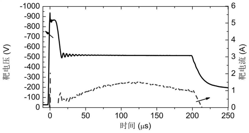
[0044] figure 2 When the power supply inductance is 50μH and the capacitive reactance of the selected capacitor is 22.5nF, at the output terminal of the power supply -500V, the waveform diagram of the target voltage and target current under the condition that the maximum oscillation voltage is -800V. When the gas is not broken down, the voltage can be maintained at -800V until the gas is broken down. Discharge conditions: the gas is argon at 0.5Pa, the target material is Cr target, the pulse width is 200μs, and the pulse frequency is 50Hz.

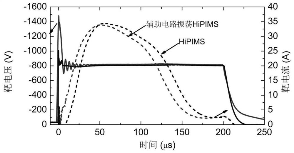
[0045] image 3 It is ordinary HiPIMS discharge and auxiliary circuit oscillating HiPIMS discharge, when the power supply inductance is 50μH, and the capacitive reactance of the selected capacitor is 22.5nF, the waveform diagram of the target voltage and target current under the condition of -800V at the output terminal of the power supply. Discharge conditions: the gas is argon at 0.5Pa, the target material is Cr target, the pulse widt...

example 2

[0055] Figure 4 It is a graph of the relationship between the current delay time and the output terminal voltage of the power supply (that is, the target voltage when the voltage is stable) in different discharge modes. The figure contains ordinary HiPIMS, with auxiliary circuit oscillating HiPIMS, whose capacitance values ​​are 22.5nF, 55nF, 110nF and 220nF respectively. Discharge conditions: the gas is argon at 0.5Pa, the target material is Cr target, the pulse width is 200μs, and the pulse frequency is 50Hz.

[0056] see Figure 4 , the scheme of example 2 replaces the capacitor 22.5nF in the scheme of example 1 with 55nF, the relationship between the current delay time and the voltage is as follows Figure 4 As shown, other steps are the same as Example 1.

example 3

[0058] see Figure 4 , the scheme of example 3 replaces the capacitor 22.5nF in the scheme of example 1 with 110nF, the relationship between the current delay time and the voltage is as follows Figure 4 As shown, other steps are the same as Example 1.


PUM


Abstract

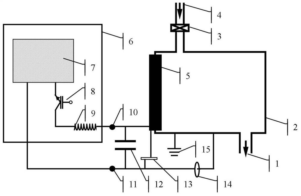
The invention provides a HiPIMS system and a method for reducing HiPIMS discharge current delay. The HiPIMS system includes a vacuum chamber and a power supply. The vacuum chamber includes a cathode target, and the power supply has an inductance at the positive output end of the power supply. A capacitor is connected in parallel between them, and the capacitor and the inductor form an LC series oscillation circuit, and the high voltage generated by the LC oscillation is used to realize rapid breakdown of the gas. In the present invention, without changing the HiPIMS power supply and additional configuration, the auxiliary circuit oscillation is used to realize rapid HiPIMS gas breakdown discharge, and the input energy to the plasma during the pulse period is increased.

Description

technical field [0001] The present invention relates to equipment and methods of magnetron sputtering, in particular to high-energy impact magnetron sputtering (HiPIMS: High-Power Impulse Magnetron Sputtering). Background technique [0002] The typical characteristics of HiPIMS (High-Power Impulse Magnetron Sputtering) technology lie in its low duty cycle (~1%), low frequency (~10-1000Hz) and high peak power (MW) pulse discharge model. Pulse discharge will inevitably face the process of gas breakdown, so compared with HiPIMS negative pulse discharge voltage, there will be a delay of several microseconds to tens of microseconds in the initial stage of discharge current, especially at relatively low voltage and pressure. Under the circumstances, it is very obvious, and there may even be a phenomenon that it cannot be discharged. In recent years, through continuous exploration of HiPIMS, researchers have found that short pulses and low pressure seem to be more beneficial to t...

Claims


Application Information

Patent Timeline
Patent Type & Authority Patents(China)
IPC IPC(8): C23C14/35C23C14/54
CPCC23C14/35C23C14/3485C23C14/54
Inventor 李刘合韩明月罗阳黄凯谢焕钧许浩徐长云
Owner BEIHANG UNIV
Learn More