A small high-low cycle composite fatigue in-situ testing machine providing orthogonal loading

An in-situ test and fatigue technology, applied in the direction of applying repetitive force/pulsation force to test the strength of materials, can solve the problems of high cost, poor economy, high manufacturing cost, etc., to avoid energy loss, stable loading path, and structural size. small effect

Active Publication Date: 2021-06-11
BEIHANG UNIV
View PDF11 Cites 1 Cited by
  • Summary
  • Abstract
  • Description
  • Claims
  • Application Information

AI Technical Summary

Problems solved by technology

Limited by the structure and loading method, it is difficult for the existing in-situ testing machine to realize the high-cycle vibration load orthogonal to the low-cycle load direction, and it is impossible to simulate the real load situation and complex stress state required by the test piece
[0004] (2) The drive mode of the low cycle drive unit is difficult to meet the requirements of the in-situ test
The low-period drive units of existing in-situ testing machines can be classified into two types: traditional motor drive and hydraulic drive, both of which are difficult to meet the requirements of in-situ testing
Limited by the driving principle, it is difficult for the motor-driven testing machine to achieve high-frequency loading, resulting in long test time and low efficiency; while the in-situ fatigue testing machine using hydraulic drive is large in size and can only be used with customized scanning Electron microscope use, poor versatility
[0005] (3) The high-cycle drive unit cannot match the in-situ test system
The existing in-situ testing machine cannot load the high-cycle load orthogonal to the direction of the low-cycle load. The reason is that the electromagnetic induction excitation principle of the traditional high-cycle load cannot be applied to the in-situ testing machine. The space electromagnetic field excited by the test area will cause strong electromagnetic interference to precision instruments and equipment such as scanning electron microscopes, making it difficult to observe the microstructure of the test piece, so it cannot meet the requirements of small-scale in-situ tests
[0006] (4) Large size and high cost
The existing electric and hydraulic fatigue testing machines are generally complex in structure and need to be equipped with a variety of accessories to be used normally, often occupying too much test space, and the manufacturing cost is high and the economy is poor

Method used


Image

  • A small high-low cycle composite fatigue in-situ testing machine providing orthogonal loading
  • A small high-low cycle composite fatigue in-situ testing machine providing orthogonal loading
  • A small high-low cycle composite fatigue in-situ testing machine providing orthogonal loading

Examples


Embodiment Construction

[0031] The present invention will be further described below in conjunction with the accompanying drawings and embodiments.

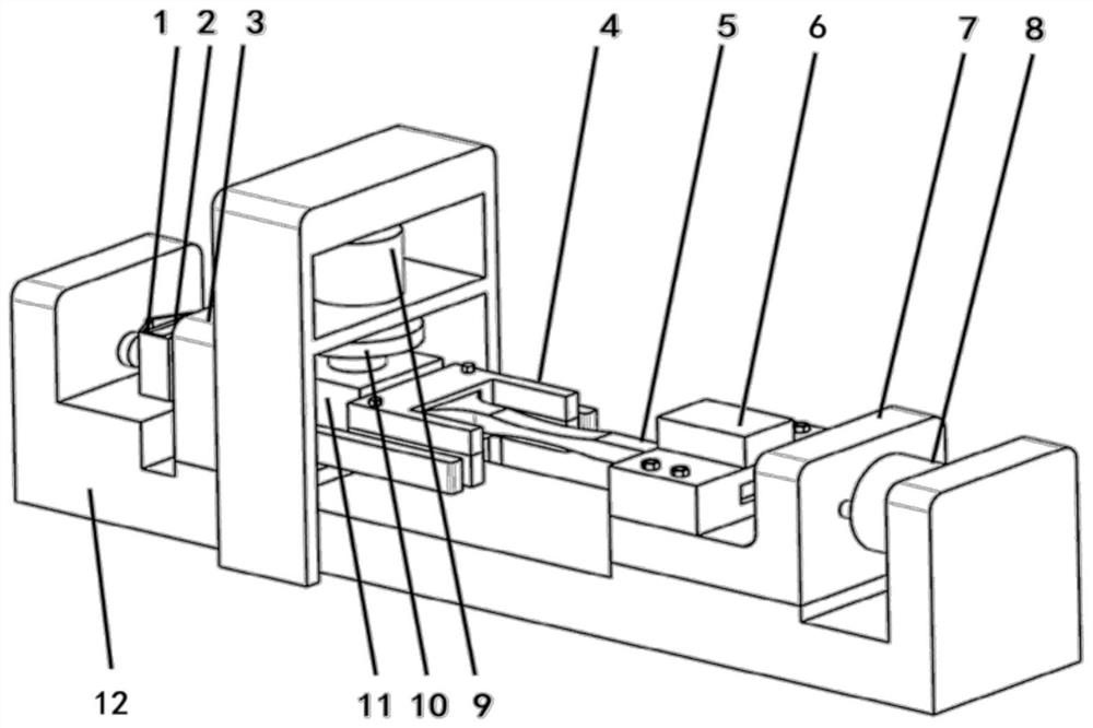
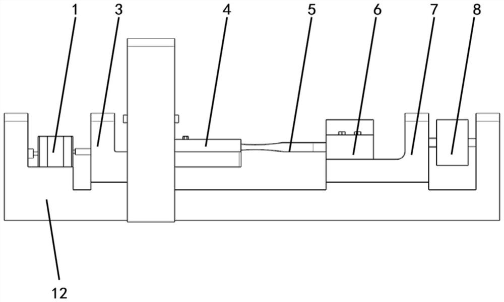
[0032] The in-situ testing machine provided by the present invention can carry out the high-low cycle composite in-situ fatigue test of orthogonal loading for the flat plate test piece, and the length direction of the test piece is defined as the axial direction (i.e. the length direction of the testing machine), and the thickness direction of the test piece ( That is, the height direction of the testing machine) is vertical.

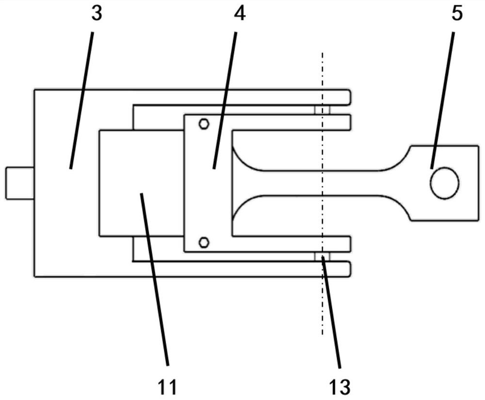
[0033] figure 1 , figure 2 The general structure of the invention is given. Among them, the load transmission mechanism 1 and the piezoelectric drive group 2 form a low-cycle drive unit, which provides low-cycle fatigue loads for the test piece 5; the dielectric elastomer 10 is a high-cycle drive unit, which provides high-cycle vibration loads for the test piece 5; Shaft clamp 3, low-circle left clamp 4, low-circumference rig...


PUM


Abstract

The invention is a small high-low cycle composite fatigue in-situ testing machine providing orthogonal loading, and relates to the technical field of material fatigue testing. The driving load is amplified by the load transfer mechanism and transmitted to the test piece to provide axial low-cycle tensile and compressive fatigue loads; the high-cycle drive unit relies on dielectric elastomers to generate high-frequency vibrations to provide vertical high-cycle fatigue loads for the test piece. Vibration fatigue load; the force sensor monitors the axial force of the test piece, the displacement sensor monitors the vibration frequency and vertical displacement, adjusts the input voltage of the high and low cycle drive unit according to the active disturbance rejection control algorithm, and accurately controls the high and low cycle load amplitude on the test piece value and frequency ratio. The testing machine of the present invention is simple in structure, small in size, stable in loading, accurate and fast, can provide high and low cycle composite fatigue loads which are orthogonally decoupled from each other, and can carry out composite fatigue in-situ tests in cooperation with a scanning electron microscope.

Description

technical field [0001] The invention relates to the technical field of material fatigue testing, in particular to a small high-low cycle composite fatigue in-situ testing machine driven by a dielectric elastic body and capable of providing orthogonal loading. Background technique [0002] Traditional material testing methods can be divided into macro-mechanical performance testing and micro-structure observation. The macro-mechanical performance test uses a universal testing machine, and the micro-structure observation requires sampling of the test piece before observation through an electron microscope. The in-situ testing machine for in-situ testing of the mechanical properties of materials from a microscopic point of view with the help of a scanning electron microscope can effectively directly investigate the microscopic characteristics and failure mechanisms of materials under various loads during the test process. It is an advanced technology in the field of material sci...

Claims


Application Information

Patent Timeline
Patent Type & Authority Patents(China)
IPC IPC(8): G01N3/32
CPCG01N3/32
Inventor 黄大伟闫晓军刘宏卓丁鑫
Owner BEIHANG UNIV
Why Eureka
Try Eureka