Two-stage photovoltaic grid-connected power generation optimization device, control system and method

A photovoltaic and voltage technology, applied in the field of two-stage photovoltaic grid-connected power generation optimization device, can solve the problems of reducing the control degree of freedom of the inverter, increasing the voltage of the medium-voltage DC bus, and reducing the service life, so as to improve the power quality, The effect of suppressing the double frequency fluctuation and improving the degree of freedom of control

Pending Publication Date: 2020-12-18
CHINA ELECTRIC POWER RES INST +2
View PDF0 Cites 0 Cited by
  • Summary
  • Abstract
  • Description
  • Claims
  • Application Information

AI Technical Summary

Problems solved by technology

[0003] However, when the AC grid voltage drops, the medium-voltage DC bus voltage of the two-stage photovoltaic grid-connected power generation system will continue to rise. After exceeding a certain limit, the photovoltaic power station will be disconnected from the grid, which does not meet the requirements of the low-voltage ride-through capability of the photovoltaic power station.
When the unbalanced voltage drops in the AC power grid, the voltage of the medium-voltage DC bus will also fluctuate at double frequency, which will increase the charge and discharge times of the equivalent capacitor of the DC bus and reduce its service life. It is also unfavorable for the normal operation of loads that require high power quality (such as DC motors, electronic precision instruments, etc.)
[0004] In the prior art, one method is to use an unloading circuit to consume the differential power on the medium-voltage DC bus during the fault ride-through period to achieve low-voltage ride-through, but the cost and heat dissipation problems of the unloading circuit are prominent; the other method is to use an inverse The inverter eliminates the rise and fluctuation of the medium-voltage DC bus voltage, but for the two-stage photovoltaic grid-connected power generation system, this method will reduce the control freedom of the inverter

Method used


Image

  • Two-stage photovoltaic grid-connected power generation optimization device, control system and method
  • Two-stage photovoltaic grid-connected power generation optimization device, control system and method
  • Two-stage photovoltaic grid-connected power generation optimization device, control system and method

Examples


Embodiment 1

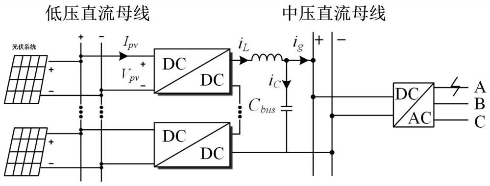
[0054] in such as figure 1 In the two-stage photovoltaic grid-connected power generation system shown, when the voltage of phase A on the AC side of the DC / AC converter drops, the voltage of the medium-voltage DC bus will rise. operation, the present invention provides a two-stage photovoltaic grid-connected power generation optimization device, such as figure 2 As shown, the device includes:

[0055] The double frequency suppression unit is used to filter out the double frequency component in the voltage of the medium voltage DC bus and the inductance current on the side of the medium voltage DC bus;

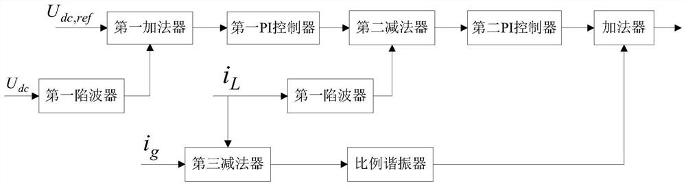
[0056] The control unit is used for filtering the voltage of the medium-voltage DC bus and filtering the double frequency according to the voltage command value of the medium-voltage DC bus, the current of the medium-voltage DC bus and the inductor current The inductor current on the side of the medium-voltage DC bus of the component determines the optimal command value of t...

Embodiment 2

[0074] Based on the same inventive concept, the present invention also provides a two-stage photovoltaic grid-connected power generation control system, such as Figure 4 As shown, the system includes:

[0075] Optimizing device as recorded in embodiment 1;

[0076] The control device is used to adjust the input current command value of the DC / DC converter in the maximum power point tracking control solar controller to the optimal command value of the input current of the DC / DC converter, and utilize the maximum power point tracking A solar controller is controlled to control the DC / DC converter.

Embodiment 3

[0078] Based on the same inventive concept, the present invention also provides a two-stage photovoltaic grid-connected power generation control method, such as Figure 5 As shown, the method includes:

[0079] Step 1. Determine the DC / DC converter connected to the photovoltaic system through the low-voltage DC bus according to the voltage of the medium-voltage DC bus, the voltage command value of the medium-voltage DC bus, the current of the medium-voltage DC bus, and the inductor current on the side of the medium-voltage DC bus The optimal command value of the input current;

[0080] Step 2. Adjust the input current command value of the DC / DC converter in the maximum power point tracking control solar controller to the optimal command value of the input current of the DC / DC converter, and use the maximum power point tracking control solar energy A controller controls the DC / DC converter.

[0081] In Embodiment 3 of the present invention, the above step 1 includes:

[0082...


PUM


Abstract

The invention relates to a two-stage photovoltaic grid-connected power generation optimization device, a control system and a method. The device comprises a double-frequency suppression unit which isused for filtering double-frequency components in the voltage of a medium-voltage direct-current bus and the inductive current of a medium-voltage direct-current bus side, and a control unit which isused forfiltering the voltage of the medium-voltage direct-current bus of the double-frequency component and the inductive current of the medium-voltage direct-current bus side of the double-frequencycomponent according to the voltage instruction value of the medium-voltage direct-current bus, the current of the medium-voltage direct-current bus and the inductive current of the medium-voltage direct-current bus side, and determining an input current optimal instruction value of a DC/DC converter connected with a photovoltaic system through a low-voltage direct-current bus. According to the invention, when a low-voltage fault occurs in two-stage photovoltaic grid-connected power generation, the double-frequency fluctuation of the voltage of the medium-voltage direct-current bus can be suppressed, and the electric energy quality of the medium-voltage direct-current bus is improved.

Description

technical field [0001] The invention relates to the technical field of new energy power generation control, in particular to a two-stage photovoltaic grid-connected power generation optimization device, control system and method. Background technique [0002] The two-stage photovoltaic grid-connected power generation system uses the medium-voltage DC bus to collect the power of the photovoltaic system in the station, and sends it to the AC grid through the grid-connected inverter, which can significantly reduce the amount of cables in the station and has higher power generation efficiency. Such as figure 1 As shown, compared with the structure of the traditional distributed inverter photovoltaic system, the two-stage photovoltaic grid-connected power generation system adds a DC / DC converter link between the photovoltaic array and the grid-connected inverter, and in order to meet the requirements of photovoltaic energy access To meet the high step-up ratio requirements of th...

Claims


Application Information

Patent Timeline
Patent Type & Authority Applications(China)
IPC IPC(8): H02J3/38H02J1/02H02J1/12
CPCH02J1/02H02J1/12H02J3/381H02J2203/20H02J2300/26Y02E10/56
Inventor 陈春萌方保民张舒捷曲立楠陈宁卢国强赵东宁杨凯璇
Owner CHINA ELECTRIC POWER RES INST
Why Eureka
Try Eureka