Control method of bidirectional charger for emergency traction of motor train unit

A control method and charging machine technology, applied in the field of rail transit, can solve the problems of trains unable to obtain electric power, line congestion, safety accidents, etc.

Pending Publication Date: 2020-12-18
CRRC QINGDAO SIFANG ROLLING STOCK RES INST
View PDF13 Cites 1 Cited by
  • Summary
  • Abstract
  • Description
  • Claims
  • Application Information

AI Technical Summary

Problems solved by technology

[0002] When the catenary fails or the pantograph of the EMU fails, the train will not be able to obtain electric energy, which will cause the traction system to fail to work normally, and the EMU will lose power. security incident

Method used


Image

  • Control method of bidirectional charger for emergency traction of motor train unit
  • Control method of bidirectional charger for emergency traction of motor train unit
  • Control method of bidirectional charger for emergency traction of motor train unit

Examples


Embodiment 1

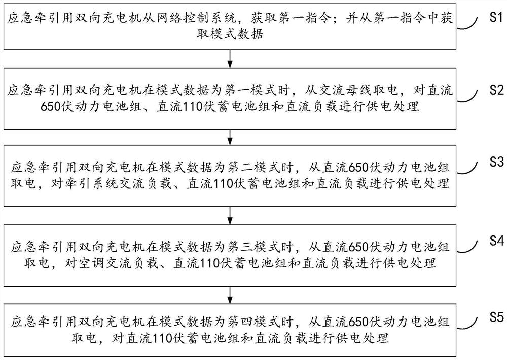
[0064] figure 1 It is a schematic diagram of the control method of the bidirectional charger for emergency traction of the EMU provided in Embodiment 1 of the present invention. The EMU involved in the embodiment of the present invention includes at least a network control system, an AC bus, a bidirectional charger for emergency traction, and a DC 110-volt battery pack , DC 650V power battery pack, DC load, traction system AC load and air conditioner AC load, etc., such as figure 1 As shown, the control method of the bidirectional charger for the emergency traction of the EMU in Embodiment 1 of the present invention includes the following steps:

[0065] S1, the two-way charger for emergency traction obtains the first command from the network control system; and obtains the mode data from the first command;

[0066] Among them, the first command includes mode data; the mode data includes the first mode, the second mode, the third mode and the fourth mode; the bidirectional ch...

Embodiment 2

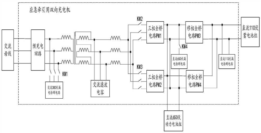
[0120] When the two-way charger works in normal mode, it takes power from the AC bus and converts AC380V into DC650V through the three-phase full-bridge circuit to charge the power battery pack, and at the same time supplies power to the subsequent phase-shifting full-bridge circuit. Due to the limited power of the circuit, the output of the three-phase full-bridge circuit should give priority to the power supply of the phase-shifted full-bridge circuit. On this basis, the charging current of the power battery cannot be greater than the maximum charging current limited by the battery management system (BATTERY MANAGEMENT SYSTEM, BMS). value. The two-way charger for emergency traction in this embodiment optimizes the PWM rectification algorithm of the three-phase full-bridge circuit. Compared with the traditional processing method in which the outer ring voltage is the set value, in order to meet the special needs of the power battery pack charging current limit, etc., Added sw...

Embodiment 3

[0135] The two three-phase full-bridge circuits inside the two-way charger for emergency traction work in mutual backup, and only one of them works at the same time. In order to avoid excessive use of one of the modules, the embodiment of the present invention uses a three-phase full-bridge circuit scheduling method. Date, cumulative running time, circuit status for scheduling.

[0136] Such as Figure 5 As shown in the schematic diagram of the three-phase full-bridge circuit scheduling method provided in Embodiment 3 of the present invention, the three-phase full-bridge circuit scheduling method in Embodiment 3 of the present invention includes the following steps:

[0137] S81. The two-way charger for emergency traction acquires the network date data from the network control system, acquires the accumulated running time data of the first circuit, the accumulated running time data of the second circuit, and the state data of the first circuit, the state data of the second cir...


PUM


Abstract

The embodiment of the invention relates to a control method of a two-way charger for emergency traction of a motor train unit. The method is applied to the motor train unit, wherein the motor train unit comprises a network control system, an alternating current bus, the two-way charger for emergency traction, a storage battery pack, a power battery pack, a direct current load, a traction system alternating current load and an air conditioner alternating current load. The method comprises the steps that four working modes are supported, and charging and discharging operation is conducted on a battery pack or a load on the motor train unit in different modes. According to the embodiment of the invention, forward charging of the storage battery pack and the power battery pack and reverse power supply of the alternating current equipment are realized, and the charging function of the motor train unit is perfected and enhanced.

Description

technical field [0001] The invention relates to the technical field of rail transit, in particular to a control method of a two-way charger for emergency traction of an EMU. Background technique [0002] When the catenary fails or the pantograph of the EMU fails, the train will not be able to obtain electric energy, which will cause the traction system to fail to work normally, and the EMU will lose power. security incident. [0003] In order to cope with this working condition, a power battery and a two-way charger can be installed in the EMU. When the EMU cannot supply power normally, the power battery can be used to drive the traction system to realize self-propelled travel. The two-way charger for emergency traction in the embodiment of the present invention is used as a new key equipment for the emergency self-propelled system. On the basis of the charging function of the original direct current (DC) 110 volt (volt, V) battery pack, a DC650V power is added. The chargi...

Claims


Application Information

Patent Timeline
IPC IPC(8): H02J9/06H02J7/10B60L50/53B60L3/00
CPCH02J9/062H02J7/06B60L50/53B60L3/0023Y02T10/70
Inventor 张波孙庆文黎梅云何欣宇赵俊博李海洋迟久鸣
Owner CRRC QINGDAO SIFANG ROLLING STOCK RES INST
Why Eureka
Try Eureka