

BUCK control circuit, BUCK control method and reference generation circuit
A technology for controlling circuits and generating circuits, which is applied in control/regulation systems, high-efficiency power electronic conversion, electrical components, etc., and can solve problems such as poor output dynamic characteristics and large no-load power consumption
- Summary
- Abstract
- Description
- Claims
- Application Information
AI Technical Summary
Problems solved by technology
Method used
Image

Examples
no. 1 example
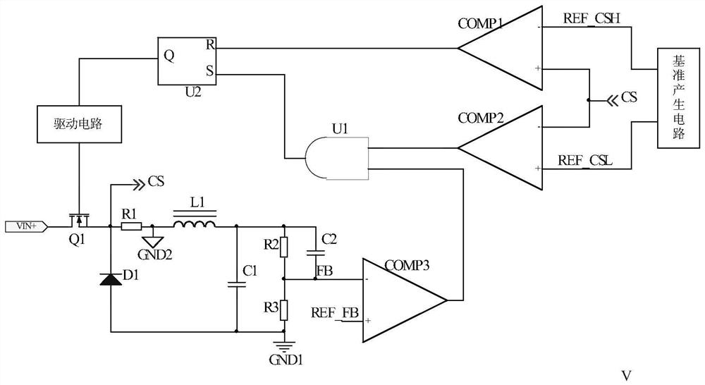
[0089] figure 1 is the circuit schematic diagram of the first embodiment, such as figure 1 As shown, the Buck circuit includes the BUCK power supply and the control circuit of the BUCK topology.
[0090] The BUCK power supply includes a switch tube Q1, a diode D1, an inductor L1 and a capacitor C1. In this embodiment, the switching transistor Q1 is a MOS transistor Q1, which is referred to as MOS transistor Q1 below.
[0091] The gate of the MOS transistor Q1 is connected to the output terminal of the drive circuit, the drain of the MOS transistor Q1 is connected to the bus voltage, the source of the MOS transistor is connected to the cathode of the diode D1; one end of the inductor L1 is connected to the cathode of the diode D1, and the other end The capacitor C1 is connected to the reference ground, and the two ends of the capacitor C1 are used as the output terminals of the BUCK power supply.
[0092] The control circuit of the BUCK topology includes a resistor R1, a res...
no. 2 example
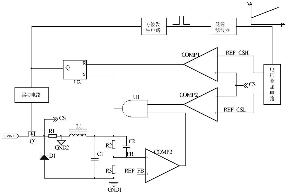
[0115] The circuit schematic diagram of the second embodiment is as follows image 3 shown. The control circuit of the BUCK topology in this embodiment includes: a resistor R1, a resistor R2, a resistor R3, a comparator COMP1, a comparator COMP2, a comparator COMP3, an AND gate U1, an RS flip-flop U2, a reference generating circuit and a driving circuit.
[0116] The resistor R1 and the inductor L1 are connected in series to detect the current of the inductor L1, and one end of the resistor R1 serves as the output terminal CS of the detection signal and is respectively connected to the negative input terminal of the comparator COMP2 and the positive input terminal of the comparator COMP1.
[0117] Resistor R2 and resistor R3 are connected in series and parallel to the output terminal of the BUCK power supply. The connection point of resistor R2 and resistor R3 is used as the output terminal FB of the feedback signal of the output voltage to be connected to the negative input t...
no. 3 example
[0133] The schematic circuit diagram of the third embodiment is as follows Figure 4 shown. A BUCK topology control circuit includes resistor R1, resistor R2, resistor R3, comparator COMP1, comparator COMP2, comparator COMP3, AND gate U1, RS flip-flop U2, a reference generating circuit and a driving circuit. Resistor R2 and resistor R3 are connected in series and parallel to the output terminal of the BUCK power supply. The connection point of resistor R2 and resistor R3 is used as the output terminal FB of the feedback signal of the output voltage to be connected to the negative input terminal of comparator COMP3. The feedback voltage reference value REF_FB is compared with Connected to the positive input terminal of the comparator COMP3, the resistor R1 is connected in series with the inductor L1 to detect the current of the inductor L1, and one end of the resistor R1 is used as the output terminal CS of the detection signal to connect with the negative input terminal of the...
PUM
 Abstract
Description
Claims
Application Information