Method for producing a micromechanical device having inclined optical windows, and corresponding micromechanical device

A manufacturing method and technology of optical windows, applied in the manufacture of microstructure devices, processes for producing decorative surface effects, microelectronic microstructure devices, etc., can solve structural damage, lack of optical quality, and very expensive three-dimensional structures, etc. problem, to achieve cost-effective, damage-prevention effect

Pending Publication Date: 2020-12-18
ROBERT BOSCH GMBH
View PDF11 Cites 0 Cited by
  • Summary
  • Abstract
  • Description
  • Claims
  • Application Information

AI Technical Summary

Problems solved by technology

[0010] The methods used to fabricate 3D structures are either very expensive or do not give the required optical quality
Furthermore, wafers with corresponding three-dimensional structures are problematic during processing, for example during wafer bonding, since the structures can easily be damaged

Method used


Image

  • Method for producing a micromechanical device having inclined optical windows, and corresponding micromechanical device
  • Method for producing a micromechanical device having inclined optical windows, and corresponding micromechanical device
  • Method for producing a micromechanical device having inclined optical windows, and corresponding micromechanical device

Examples


Embodiment Construction

[0033] In the figures, identical reference numbers indicate identical or functionally identical elements.

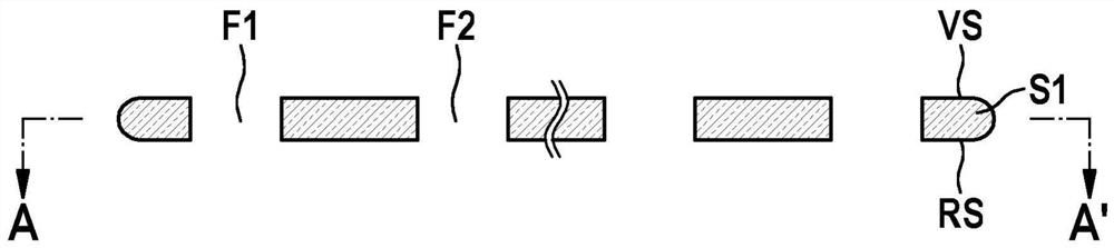
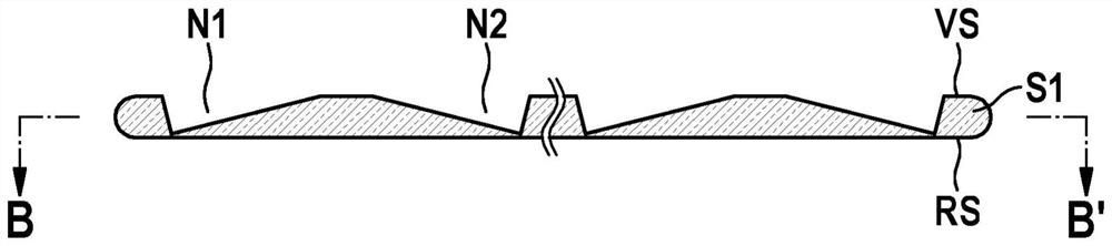
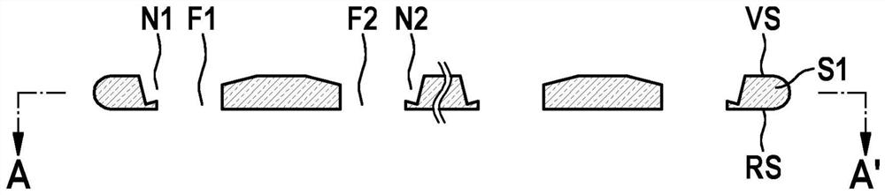
[0034] Figure 1a )-e) are schematic cross-sectional views for explaining the manufacturing method for a micromechanical device with a tilted optical window and the corresponding micromechanical device according to the first embodiment of the present invention, and figure 2 is a schematic top view of the micromechanical device according to the first embodiment of the present invention.

[0035] The micromechanical device with inclined optical windows according to the first embodiment can be used, for example, as a protective wafer device for a micromechanical micromirror scanner device.

[0036] The production of the micromechanical device takes place on a wafer plane, but the production is not restricted thereto and can also take place on another substrate plane. To simplify the illustration, only the production of two tilted optical windows is shown here, but a large...


PUM


Abstract

The invention provides a method for producing a micromechanical device having inclined optical windows, and a corresponding micromechanical device. The production method comprises the following steps:providing a first substrate (S1) having a front side (VS) and a rear side (RS); forming a plurality of spaced-apart through holes (F1, F2) in the first substrate (S1), which are arranged along a plurality of spaced-apart rows (R1, R2) in the first substrate (S1); forming a relevant continuous oblique groove (N1, N2) along each of the rows (R1, R2), these grooves defining a seat for the inclined optical windows (G1, G2); and inserting the optical windows (G1, G2) above the through holes (F1, F2) into the grooves (N1, N2).

Description

technical field [0001] The invention relates to a production method for a micromechanical device with an inclined optical window and to a corresponding micromechanical device. Background technique [0002] Although any desired optical devices and systems can also be used, the invention and the problem underlying the invention are explained with reference to an optical micromechanical micromirror scanner device. [0003] Micromechanical MEMS components must be protected against harmful external environmental influences (eg moisture, aggressive media, etc.). Also necessary is protection against mechanical contact / damage and in order to achieve separation of the wafer assembly into chips by sawing. In many cases the setting of a defined atmosphere (for example gas type and / or gas pressure) must also be possible through tight packaging. [0004] The packaging of MEMS components in wafer composite structures with cap wafers with cavities and vias has been set up in detail. For...

Claims


Application Information

Patent Timeline
Patent Type & Authority Applications(China)
IPC IPC(8): B81C1/00
CPCB81B2201/042B81C1/00317B81C2203/0118B81C2203/032B81C2203/036B81C2203/054B81B7/0067
Inventor B·施托伊尔S·平特
Owner ROBERT BOSCH GMBH
Why Eureka
Try Eureka