Laser projection equipment

A laser projection and equipment technology, applied in optics, instruments, projection devices, etc., can solve the problems of difficult estimation of loss rate, large light loss, and large red laser light loss, and achieve the effect of good color and small light loss

Active Publication Date: 2020-12-22
QINGDAO HISENSE LASER DISPLAY CO LTD
View PDF13 Cites 1 Cited by
  • Summary
  • Abstract
  • Description
  • Claims
  • Application Information

AI Technical Summary

Problems solved by technology

Among them, due to the different luminescent mechanism, such as Figure 17 As shown, the red laser light-emitting chip has two light-emitting points, but one light-emitting chip corresponds to one collimating lens, so the effect of one collimating lens on collimating two light-emitting points is worse than that of one collimating lens on The collimation effect of a light-emitting point makes the divergence angle of the red laser light from the light-emitting surface of the laser component larger than that of the other two color lasers. However, in practical applications, the optical path system is shared by the three-color lasers. During the beam transmission process Among them, the optical lenses experienced usually have their own light collection range or have high light processing efficiency within a certain angle range, while for red lasers, due to the faster divergence, the light beam in a large angle range is easily lost. Therefore, the light loss of the red laser is usually large, and this loss rate is difficult to estimate, and it is difficult to solve it by power compensation
[0004] It is necessary to propose a solution to solve the problem that the red laser light loss is large in the three-color laser application, which leads to the imbalance of the color ratio of the system and the poor quality of the projected picture

Method used


Image

  • Laser projection equipment
  • Laser projection equipment
  • Laser projection equipment

Examples


Embodiment Construction

[0059] In order to make the purpose, technical solutions and advantages of the embodiments of the present invention clearer, the technical solutions in the embodiments of the present invention will be clearly and completely described below in conjunction with the drawings in the embodiments of the present invention. Obviously, the described embodiments It is a part of embodiments of the present invention, but not all embodiments. Based on the embodiments of the present invention, all other embodiments obtained by persons of ordinary skill in the art without creative efforts fall within the protection scope of the present invention.

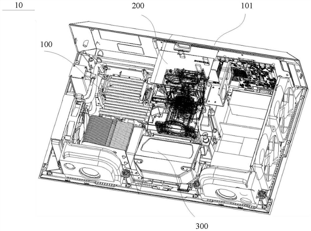
[0060] first according to figure 1 The shown laser projection device is used to illustrate the structure and working process of the laser projection device in this embodiment.

[0061] figure 1 It shows a schematic structural diagram of a laser projection device. The laser projection device 10 includes a complete machine housing 101, and accor...


PUM

PropertyMeasurementUnit
poweraaaaaaaaaa
poweraaaaaaaaaa
poweraaaaaaaaaa

Abstract

The invention provides laser projection equipment. The laser projection equipment comprises a complete machine shell and a light source, the light source comprises a red laser assembly and a green laser assembly which are installed in parallel, and a blue laser assembly perpendicular to the red laser assembly and the green laser assembly. A first light combination mirror is arranged at the intersection of the blue laser and the green laser, the first light combination mirror transmits the blue laser and reflects the green laser, a second light combination mirror is arranged at the intersectionof the blue laser, the green laser and the red laser after light combination, and the second light combination mirror transmits the red laser and reflects the blue laser and the green laser to a third light combination mirror. The third light combination mirror reflects the red laser, the blue laser and the green laser to a light source light outlet, and the first light combination mirror, the second light combination mirror and the third light combination mirror are arranged in parallel. According to the laser projection equipment, the light loss of the red laser is small, the power ratio orcolor ratio of the three-color laser beams can be maintained, and the laser projection equipment can present a projection picture with high brightness and good color.

Description

technical field [0001] The invention relates to the technical field of laser projection display, in particular to a laser projection device. Background technique [0002] The laser light source has the advantages of good monochromaticity, high brightness, and long life, and is an ideal light source. As the power of laser devices increases to meet the requirements of industrial applications, lasers are gradually being used as light sources for lighting. For example, in recent years, lasers have been used as projection light sources in projection equipment, gradually replacing mercury lamp lighting. Compared with LED light sources, lasers also have the advantages of small etendue and high brightness. [0003] Lasers are divided into blue lasers, red lasers and green lasers according to the type of light emitting, which emit blue lasers, red lasers and green lasers respectively. Among them, due to the different luminescent mechanism, such as Figure 17 As shown, the red laser...

Claims


Application Information

Patent Timeline
Patent Type & Authority Applications(China)
IPC IPC(8): G03B21/20
CPCG03B21/2013G03B21/2033G03B21/208G03B21/2066G03B21/20
Inventor 颜珂田有良
Owner QINGDAO HISENSE LASER DISPLAY CO LTD
Why Eureka
Try Eureka