Supercharge Your Innovation With Domain-Expert AI Agents!

Battery-free power supply method and circuit design

A power supply method and circuit design technology, which is applied in the direction of battery circuit devices, circuit devices, collectors, etc., can solve the problems that the whole machine product cannot be powered on normally, the power chip cannot be started normally, and consumes a large current, etc., to achieve saving Product cost and size, low power consumption, ensure full utilization of the effect

Pending Publication Date: 2020-12-22
华大恒芯科技有限公司
View PDF0 Cites 0 Cited by
  • Summary
  • Abstract
  • Description
  • Claims
  • Application Information

AI Technical Summary

Problems solved by technology

[0006] However, in practical application scenarios, in order to better optimize product cost and mechanical size, it is often inclined to choose a small-sized solar panel. At this time, the output power of the solar panel will decrease. Whether it is the capacitance of the internal and peripheral components of the power chip or the capacitance of the post-load circuit, it will consume a large current at the moment when it is just started, and at this time the voltage of the supercapacitor just reaches the power startup threshold. Whether it is due to the limitation of its own output power characteristics or external environment changes (such as changes in light intensity, changes in light-receiving area, etc.) that it cannot provide a certain current, it may cause the voltage of the super capacitor to drop below the shutdown voltage of the power chip. The chip cannot be started normally, and the above process may be repeated continuously afterwards, that is, the voltage of the supercapacitor is constantly changing between the power startup threshold and the shutdown threshold, showing a phenomenon similar to "hiccups", resulting in the failure of the whole machine to start normally. electrical work

Method used


Image

  • Battery-free power supply method and circuit design
  • Battery-free power supply method and circuit design

Examples


Embodiment Construction

[0049] The examples given are for better description of the present invention, but the content of the present invention is not limited to the examples given. Therefore, non-essential improvements and adjustments made by those skilled in the art to the embodiments according to the content of the invention above still belong to the protection scope of the present invention.

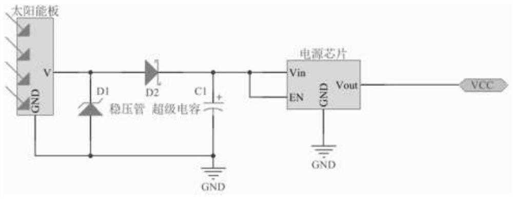
[0050] The power source of this embodiment is a solar panel.

[0051] The power supply chip in this embodiment is a DCDC chip, Vin is a power stage input, Vout is a power stage output, and EN is enable.

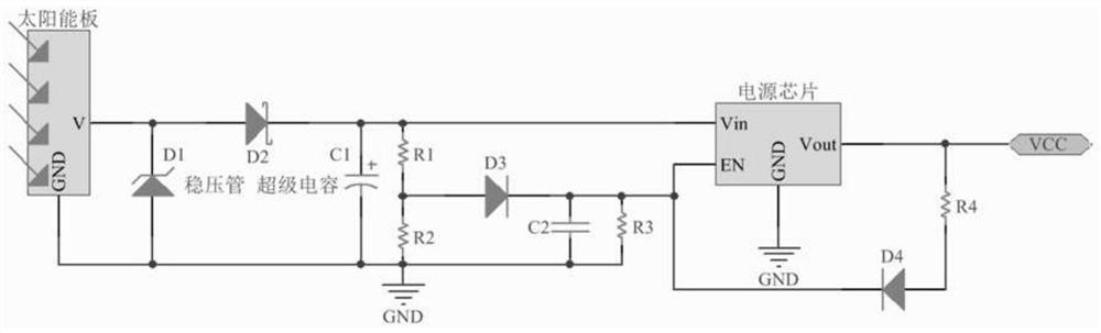
[0052] The present invention provides a circuit design without battery power supply, such as figure 2 As shown, the circuit includes: a capacitor charging module, a Vin voltage divider module and a VCC feedback module.

[0053] The capacitor charging module is specifically: the anode of the power supply is connected to the anode of the diode D2 to output current, and the current enters the capacitor C1 ...


PUM


Abstract

The invention belongs to the field of circuit design, and particularly relates to a battery-free power supply method and circuit design. According to the invention, an EN (enable) pin of a power supply chip is controlled by adopting two voltage signals, when the power supply chip is in a turn-off state, if the energy storage capacitor is charged at the moment, the input voltage of the power supplychip is subjected to voltage division by adopting the resistor, and then the power supply chip is controlled by the EN pin to be restarted after the super capacitor stores more electric quantity; when the power supply chip works normally, the output voltage of the power supply chip is fed back to the EN pin to form a self-locking function, so that the power supply chip is prevented from being turned off in advance in the discharge process of the super capacitor; when the input voltage of the power supply chip is gradually reduced to the chip starting threshold, the circuit is automatically unlocked to ensure that the circuit can be normally started again in the next charging process. The circuit design provided by the invention is low in cost and low in power consumption, solves the problem of power supply starting when a charging device is in a low-power state, and can also fully utilize the super capacitor to store electric quantity.

Description

technical field [0001] The invention belongs to the field of circuit design, and in particular relates to a battery-free power supply method and circuit design. Background technique [0002] Solar energy is a renewable energy source, which is generally used in modern times to generate electricity or provide energy for water heaters. When solar energy is used as power supply, the power supply circuit built by solar panel + super capacitor + power chip is generally used. The simplest low-cost circuit structure, such as figure 1 shown. [0003] At this time, the main function of the voltage regulator D1 is to limit the output voltage of the solar panel to prevent it from exceeding the allowable working voltage of the subsequent supercapacitor; the main function of the diode D2 is to prevent the electricity stored in the supercapacitor from leaking back to the front class devices, resulting in an unnecessary increase in static power consumption. [0004] For example, the maxi...

Claims


Application Information

Patent Timeline
Patent Type & Authority Applications(China)
IPC IPC(8): H02J7/35H02J7/34H02M1/36H02M1/32H02J50/00
CPCH02J7/345H02J7/35H02M1/32H02M1/36H02J50/00
Inventor 王宇飞马纪丰张建平
Owner 华大恒芯科技有限公司
Features
  • R&D
  • Intellectual Property
  • Life Sciences
  • Materials
  • Tech Scout
  • Unparalleled Data Quality
  • Higher Quality Content
  • 60% Fewer Hallucinations
Learn More