A kind of circular seam butt welding method of seamless steel pipe

A seamless steel pipe and butt welding technology, applied in welding equipment, tubular articles, arc welding equipment, etc., can solve the problems of many incomplete penetration defects, poor inner wall formation, cutting and re-welding, etc., to reduce the amount of filler metal, Improve the welding efficiency and the effect of forming flat

Active Publication Date: 2022-04-29
TIANJIN UNIV
View PDF6 Cites 0 Cited by
  • Summary
  • Abstract
  • Description
  • Claims
  • Application Information

AI Technical Summary

Problems solved by technology

[0003] For this reason, it is necessary to solve the problems of rework, cutting off and rewelding caused by poor inner wall formation and many incomplete penetration defects in the construction technology of existing steel catenary risers.

Method used


Image

  • A kind of circular seam butt welding method of seamless steel pipe
  • A kind of circular seam butt welding method of seamless steel pipe

Examples


Embodiment 1

[0027] Embodiment 1 The circular seam butt welding method of the steel catenary riser with remote observation and adjustment of the welding torch position and posture by the welder

[0028] like Figure 1-2 As shown, a circular seam butt welding method in the construction of steel catenary riser pipe laying for the development of deep sea oil and gas resources, including:

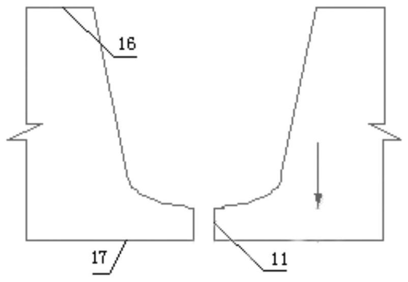
[0029] Groove processing: Groove processing is carried out on the welding joint of the steel catenary riser to be welded, and the groove is processed into such as figure 2 The U-shaped shown; the U-shaped groove is arranged at the corresponding welding place of the pipe end, and the blunt edge thickness 11 of the U-shaped groove is 3mm, and the assembly accuracy when the two pipes are assembled (ie figure 1 The narrow gap between the U-shaped bottom grooves) is controlled within 1.0mm;

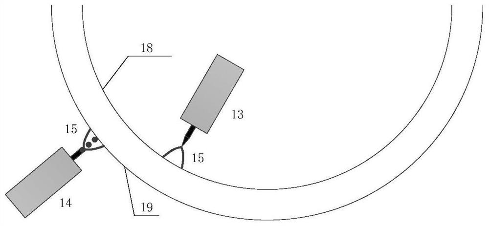
[0030] Inner wall self-fluxing bottom welding: the automatic tungsten inert gas shielded welding torch installed on th...

Embodiment 2

[0032] Embodiment 2 The girth butt welding method of a high-strength pipeline that adopts seam tracking + arc voltage tracking to adjust the welding torch position and posture

[0033] Similar to Example 1, the high-strength pipeline girth butt welding is carried out, the difference is that in the step of "self-fluxing welding the inner wall of the groove", the automatic tungsten inert gas shielded welding torch is not real-time according to the results of the welder's remote observation. Instead of adjusting the pose, weld seam tracking and arc voltage tracking are used to adjust the pose in real time, that is, to use industrial cameras or line structured light to visually track the shape of the inner wall of the groove, and at the same time use the arc pressure sensor to monitor the automatic tungsten inert gas Protect the height of the welding torch from the inner wall of the groove. When the narrow gap of the U-shaped groove and the size change of the wrong side are detecte...

Embodiment 3

[0034] Embodiment 3 The circular seam butt welding method of the tension leg of the inner and outer walls of the groove welded in steps

[0035] Similar to Example 1, the circular seam butt welding in tension leg construction is carried out for the development of deep-sea oil and gas resources, the difference is that the "inner wall self-fluxing bottom welding" and the "outer wall groove welding" are not performed simultaneously. Filling welding" step, but after the "groove inner wall self-fluxing root welding" is all completed, then the "outer wall groove filling welding" step is carried out.


PUM

PropertyMeasurementUnit
thicknessaaaaaaaaaa

Abstract

The invention discloses a method for circular seam butt welding of seamless steel pipes, which comprises: processing a U-shaped groove on the welded joint of a seamless steel pipe to be welded; using an automatic tungsten inert gas shielded welding torch to perform self-fluxing welding on the inner wall of the groove, according to The welder remotely observes or adopts seam tracking and arc voltage tracking to adjust the position and posture of the welding torch in real time; the gas shielded welding torch is used to perform filling and capping welding in the groove of the outer wall of the pipeline. The "inner wall self-fluxing root welding" and the "outer wall groove filling welding" steps can be performed at the same time, or the "outer wall groove filling welding" step can be performed after all self-fluxing welding of the inner wall of the groove is completed.

Description

technical field [0001] The invention relates to a method for circular seam butt welding of seamless steel pipes, in particular to a method for circular seam butt welding in the construction of steel catenary riser pipe laying for the development of deep sea oil and gas resources. Background technique [0002] Steel catenary riser laying technology has won the favor of deepwater development due to its relatively simple manufacturing process and low cost. However, the complex marine environment and increasing production requirements pose more challenges for the design and manufacture of deepwater steel catenary risers. As the water depth increases and the length of the riser increases, the marine environment becomes more severe. The generation of underwater vortex-induced vibrations will cause severe vibrations perpendicular to the water flow and the axis of the cylinder. At the same time, the steel catenary riser passes through the joint and the platform. The effect of alter...

Claims


Application Information

Patent Timeline
Patent Type & Authority Patents(China)
IPC IPC(8): B23K9/167B23K9/173B23K9/028B23K33/00B23K101/06
CPCB23K9/167B23K9/173B23K9/0282B23K33/004B23K2101/06
Inventor 程方杰武少杰王东坡
Owner TIANJIN UNIV
Why Eureka
Try Eureka