Intelligent multifunctional sewing machine
A multi-functional, sewing machine technology, applied in the direction of sewing machine components, sewing machine control devices, sewing machine thread cutting mechanism, etc., can solve the problems of increased cost of sewing machine, shortened service life of sewing machine, decreased power utilization rate, etc., to achieve improved The level of intelligent control, the realization of programmed control, and the effect of improving the performance of the whole machine
- Summary
- Abstract
- Description
- Claims
- Application Information
AI Technical Summary
Problems solved by technology
Method used
Image
Examples
Embodiment 1
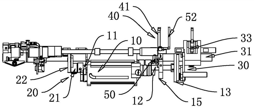
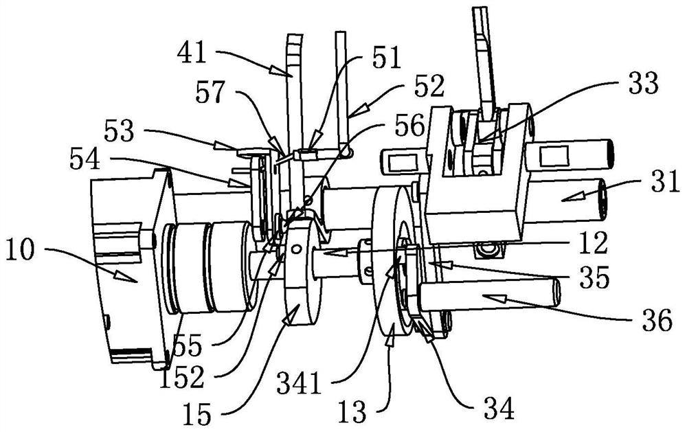
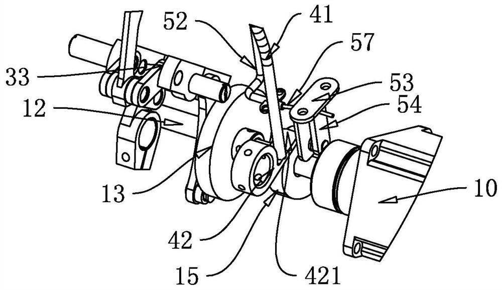
[0028] figure 1 It is a schematic diagram of an intelligent multifunctional sewing machine of the present application, which has a power source 10. The power source 10 is a power device with dual output power. The power source 10 has a front output shaft 11 and a rear output shaft 12. The power source 10 rotates and drives the front The output shaft 11 and the rear output shaft 12 are rotated. The power source 10 of the present application controls the thread trimming action of the thread trimming mechanism 20 through the front output shaft 11 , and controls the reverse stitch adjustment mechanism 30 , the presser foot lifting mechanism 40 and the thread release mechanism 50 through the rear output shaft 12 . Needle distance adjustment action, presser foot lift action and thread release action; achieve the technical effect that the above-mentioned sewing actions are completed by one power source 10 at different times and in different areas, so that the sewing machine has the p...
Embodiment 2
[0047] The second embodiment is basically the same as the above-mentioned first embodiment, the difference is that the rear output shaft 12 controls the reverse stitch length adjustment mechanism 30 , the presser foot lifting mechanism 40 and the thread release mechanism 50 . , Lifting the presser foot and loosening the thread, the rear output shaft 12 is fixed with a composite transmission wheel 13 and a presser foot lifting thread cam 15. This solution does not have a separate thread trimming mechanism 20, and other contents are the same as in the first embodiment. The technical effect is the same.
Embodiment 3
[0049] The third embodiment is basically the same as the above-mentioned first embodiment, the difference is that the composite transmission wheel 13 is arranged in a separate type, and the Figure 8 Figure 9 Figure 10 Among them, the composite transmission wheel is divided into three parts, which are composed of a composite transmission wheel inner limiting plate 1a3, a composite transmission wheel base plate 1b3 and a composite transmission wheel outer buckle plate 1c3, but the above-mentioned composite transmission is still required to realize the scheme of the present application. The wheel inner limiting plate 1a3, the composite transmission wheel base plate 1b3 and the composite transmission wheel outer gusset plate 1c3 are recombined into a whole to become a complete composite transmission wheel to realize the function of the first embodiment. There are various methods to make the composite transmission wheel inner limit plate 1c3 1a3 and the outer gusset plate 1c3 o...
PUM
 Abstract
Description
Claims
Application Information
 - R&D
- Intellectual Property
- Life Sciences
- Materials
- Tech Scout
- Unparalleled Data Quality
- Higher Quality Content
- 60% Fewer Hallucinations
Browse by: Latest US Patents, China's latest patents, Technical Efficacy Thesaurus, Application Domain, Technology Topic, Popular Technical Reports.
© 2025 PatSnap. All rights reserved.Legal|Privacy policy|Modern Slavery Act Transparency Statement|Sitemap|About US| Contact US: help@patsnap.com


