A low-voltage switchgear cabinet

A low-voltage switchgear and cabinet body technology, which is applied in the direction of pull-out switchgear, switchgear, switchgear components, etc., can solve the problem that the abnormal heat of the switchgear cannot be effectively dealt with

Active Publication Date: 2022-07-05
CHONGQING WANGBIAN ELECTRIC GRP CORP
View PDF17 Cites 0 Cited by
  • Summary
  • Abstract
  • Description
  • Claims
  • Application Information

AI Technical Summary

Problems solved by technology

[0004] The present invention intends to provide a low-voltage switch cabinet body to solve the problem that the internal structure of the switch cabinet body cannot effectively deal with the abnormal heating of the switch cabinet

Method used


Image

  • A low-voltage switchgear cabinet
  • A low-voltage switchgear cabinet
  • A low-voltage switchgear cabinet

Examples


Embodiment 1

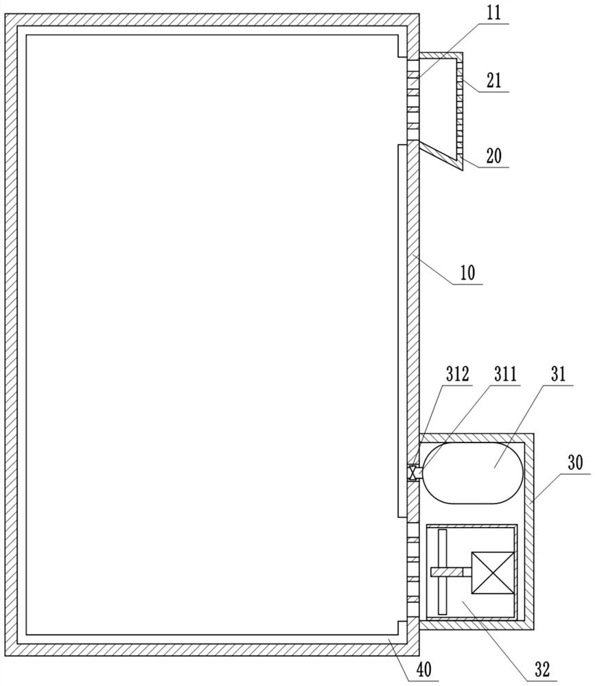
[0027] This embodiment is basically as figure 1Shown: a low-voltage switch cabinet cabinet, including a cabinet body 10 and a drawer 50 that can be pulled relative to the cabinet body 10. The cabinet body 10 is made of aluminum-zinc coated plate, which has high hardness and is not easy to deform. , has the characteristics of corrosion resistance and oxidation resistance, it is more suitable to use aluminum-zinc plate to process the cabinet body 10. A heat dissipation port 11 is opened on the side wall of the cabinet body 10 , a buffer chamber 20 opposite to the heat dissipation port 11 is welded on the outer wall of the cabinet body 10 , and a heat dissipation hole 21 is opened on the side wall of the buffer chamber 20 opposite to the heat dissipation port 11 . . The bottom of the buffer chamber 20 is inclined downward to the side away from the cabinet body 10 . After the external dust and rainwater enter the buffer chamber 20 , they will move along the bottom of the buffer c...

Embodiment 2

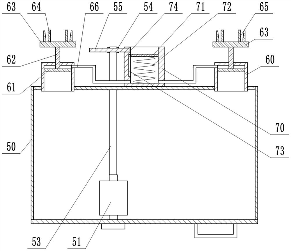
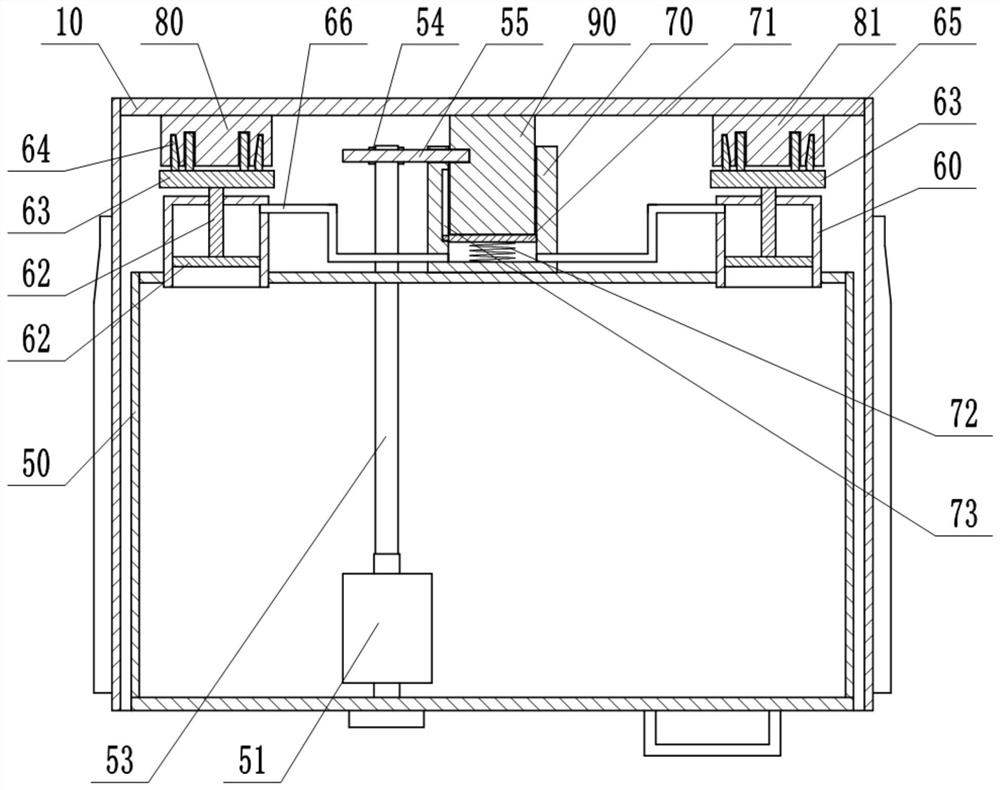
[0031] The difference between this embodiment and the first embodiment is that: figure 2 , 3 As shown, piston cylinders 60 are fixedly installed on both sides of the rear side wall of the drawer 50 , and one end of the piston cylinder 60 close to the drawer 50 is open. A piston 61 is slidably connected to the piston cylinder 60, and a support rod 62 that passes through the piston cylinder 60 and can be sealedly connected to the piston cylinder 60 is fixed on the piston 61, and a mounting seat 63 located outside the piston cylinder 60 is welded on the support rod 62. , one of the mounting bases 63 is fixedly mounted with an incoming line moving contact 64 , and the other mounting base 63 is fixedly mounted with an outgoing line moving contact 65 . A sleeve 70 is also fixed on the rear side wall of the drawer 50. The sleeve 70 is fixed between the two piston cylinders 60. The sleeve 70 is open at one end away from the drawer 50, and the sleeve 70 is filled with hydraulic oil. ...


PUM


Abstract

The invention belongs to the technical field of electrical equipment, and in particular relates to a low-voltage switchgear cabinet, comprising a cabinet body and a drawer that can be pulled out relative to the cabinet body. The cabinet body is provided with a temperature tester and an alarm unit; An airbag layer is provided, and a first solenoid valve is arranged on the airbag layer; a heat dissipation chamber that can communicate with the interior of the cabinet body is provided on the outside of the cabinet body, and the heat dissipation chamber is provided with a heat dissipation fan, a liquid nitrogen bottle and a controller; liquid nitrogen The bottle is connected with an exhaust pipe that can communicate with the airbag layer, and the exhaust pipe is provided with a second solenoid valve. The use of the technical solution can effectively solve the problem that the internal structure of the switch cabinet cannot effectively cope with the abnormal heating of the switch cabinet.

Description

technical field [0001] The invention belongs to the technical field of electrical equipment, and particularly relates to a low-voltage switchgear cabinet. Background technique [0002] Low-voltage switchgear is suitable for power plants, petroleum, chemical, metallurgy, textile, high-rise buildings and other industries, as power transmission, distribution and power conversion. As an important equipment for power distribution, low-voltage switchgear plays an important role in modern distribution network and engineering construction. [0003] There are a variety of electrical components inside the low-voltage switchgear, which will generate a lot of heat during operation, causing the temperature inside the low-voltage switchgear to rise. When the ambient temperature is high, it is not conducive to the work of the internal electrical components, and sometimes even burns the electrical components. In view of the above problems, the technical problem is solved by providing a hea...

Claims


Application Information

Patent Timeline
Patent Type & Authority Patents(China)
IPC IPC(8): H02B1/56H02B1/30H02B1/36H02B1/28H02B11/133H02B11/02F25D3/10G08B21/24G08B3/10
CPCH02B1/56H02B1/30H02B1/36H02B1/28H02B11/133H02B11/02F25D3/10G08B21/24G08B3/10
Inventor 彭信尧曹健廖勇吴路波张强伍玉超田元丰蒋跃精廖伟雄黎各强徐超
Owner CHONGQING WANGBIAN ELECTRIC GRP CORP
Why Eureka
Try Eureka