Integrated multifunctional photocatalysis experiment system

A technology of multifunctional catalysis and experimental system, applied in the field of integrated multifunctional photocatalytic experimental system

Pending Publication Date: 2021-01-01
WUHAN TEXTILE UNIV
View PDF0 Cites 1 Cited by
  • Summary
  • Abstract
  • Description
  • Claims
  • Application Information

AI Technical Summary

Problems solved by technology

[0004] The purpose of the present invention is to solve the problem of enhancing the controllability of functions, reducing the complexity of each subsystem component, and keeping the system running stably for a long time as much as possible on the basis of ensuring complete functions, especially maintaining the output power of the light source Due to the lack of stability for a long time, an integrated multifunctional photocatalytic experimental system is proposed

Method used


Image

  • Integrated multifunctional photocatalysis experiment system
  • Integrated multifunctional photocatalysis experiment system
  • Integrated multifunctional photocatalysis experiment system

Examples


Embodiment 1

[0062] Using UV-light, namely ultraviolet light:

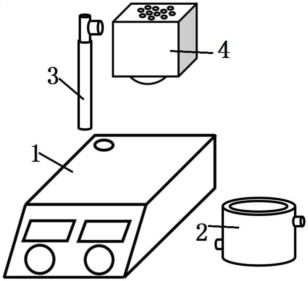
[0063] In the experiment, put 50mg of bismuth oxychloride into the photocatalytic degradation reactor, then add 100mL rhodamine B simulated pollutant solution with a concentration of 20mg / L, and place it in a multifunctional integrated photocatalytic experiment designed by the present invention. On the magnetic stirrer of the system, stir at a speed of 500r / min for 2h, including dark reaction for 1h, using a 50W 365-370nm LED light source. During the reaction, the dark reaction is sampled every 30min, and the light reaction is sampled every 10min. 1.0 mL was sampled each time. After sampling, use a UV spectrophotometer to detect the degradation effect of Rhodamine B. For the specific effect, refer to Image 6 .

Embodiment 2

[0065] Using IR-light, namely infrared light:

[0066] In the experiment, put 50mg of chlorine oxidation into the photocatalytic degradation reactor, then add 100mL rhodamine B simulated pollutant solution with a concentration of 20mg / L, and place it in a multifunctional integrated photocatalytic experimental system designed by the present invention On a magnetic stirrer, stir at a speed of 500r / min for 2 hours, including dark reaction for 1 hour, using a 50W 850nm LED light source. During the reaction, the dark reaction is sampled every 30 minutes, and the light reaction is sampled every 10 minutes. 1.0mL. After sampling, use a UV spectrophotometer to detect the degradation effect of Rhodamine B. For the specific effect, refer to Image 6 .

Embodiment 3

[0068] Using Vis-light, both visible light

[0069] In the experiment, put 50mg of chlorine oxidation into the photocatalytic degradation reactor, then add 100mL rhodamine B simulated pollutant solution with a concentration of 20mg / L, and place it in a multifunctional integrated photocatalytic experimental system designed by the present invention On a magnetic stirrer, at a speed of 500r / min, stir for 2h, and dark reaction for 1h, choose 50W 410-420nm LED light source, during the reaction process, dark reaction is sampled every 30min, and light reaction is sampled every 10min. Sampling 1.0mL. After sampling, use a UV spectrophotometer to detect the degradation effect of Rhodamine B. For the specific effect, refer to Image 6 with Figure 7 In The new Device curve.


PUM

PropertyMeasurementUnit
diameteraaaaaaaaaa
heightaaaaaaaaaa

Abstract

The invention discloses an integrated multifunctional photocatalysis experiment system, and belongs to the field of photocatalysis. The integrated multifunctional photocatalysis experiment system comprises a magnetic stirrer, a photocatalytic degradation reactor arranged on the magnetic stirrer, and a light source. The light source arranged above the photocatalytic degradation reactor is used forproviding an irradiation light source for the photocatalytic degradation reactor, and the light source adopts a replaceable long-life LED light source; and the specific use process comprises the following steps: putting bismuth oxychloride into the photocatalytic degradation reactor, then adding a simulated pollutant solution, putting the photocatalytic degradation reactor into the magnetic stirrer, and performing stirring for 1.5-3 hours at a rotating speed of 300-2000r/min, carrying out the dark reaction for 0.8-1.2 h, selecting LED light sources with different wavelengths, in the reaction process, carrying out sampling once every 28-32 min in the dark reaction, and carrying out sampling once every 8-12 min in the light reaction; the system has the advantages of compact and small system,simplicity in operation, convenience in operation and maintenance, long service life, high reliability and the like, and has excellent practicability and universality.

Description

technical field [0001] The invention relates to the technical field of photocatalysis, in particular to an integrated multifunctional photocatalysis experiment system. Background technique [0002] With the wide application of semiconductor materials, the use of photocatalysis is increasing; semiconductor photocatalytic materials use light sources of specific wavelengths to produce catalysis under the irradiation of light sources, and use light to excite photogenerated holes with oxidizing ability or photogenerated electrons with reducing ability. , so it has a wide range of prospects in the fields of artificial photosynthetic nitrogen fixation, CO2 photoreduction, organic photochemical synthesis, photocatalytic hydrogen production, photocatalytic oxygen production, photocatalytic pollutant degradation, and nanocatalytic medicine. [0003] Therefore, the photocatalytic reaction system needs to be able to better meet various conditions. On the basis of ensuring complete funct...

Claims


Application Information

Patent Timeline
Patent Type & Authority Applications(China)
IPC IPC(8): B01J8/10
CPCB01J8/10
Inventor 徐海明夏东升李东亚夏欢秦海兰
Owner WUHAN TEXTILE UNIV
Why Eureka
Try Eureka