
Device and method for continuously preparing azo compound

A technology of azo compounds and storage tanks, applied in chemical instruments and methods, feeding devices, chemical/physical processes, etc., to achieve continuous synthesis, compact overall structure, and eliminate the impact of inaccurate material matching on product quality Effect

Active Publication Date: 2021-01-05
SHENYANG RES INST OF CHEM IND
View PDF6 Cites 0 Cited by
  • Summary
  • Abstract
  • Description
  • Claims
  • Application Information

AI Technical Summary

Problems solved by technology

[0008] The purpose of the present invention is to provide a device and method for continuous preparation of azo compounds, which can realize the coupling of micro-collision flow and stirring system for the process of producing high-viscosity materials by rapid reaction of low-viscosity liquid-liquid system, and the collision and mixing will not Affected by the stirring system, it effectively prevents the clogging problem, strengthens the mass transfer, and improves the mixing efficiency

Method used


Image

  • Device and method for continuously preparing azo compound
  • Device and method for continuously preparing azo compound
  • Device and method for continuously preparing azo compound

Examples


Embodiment 1

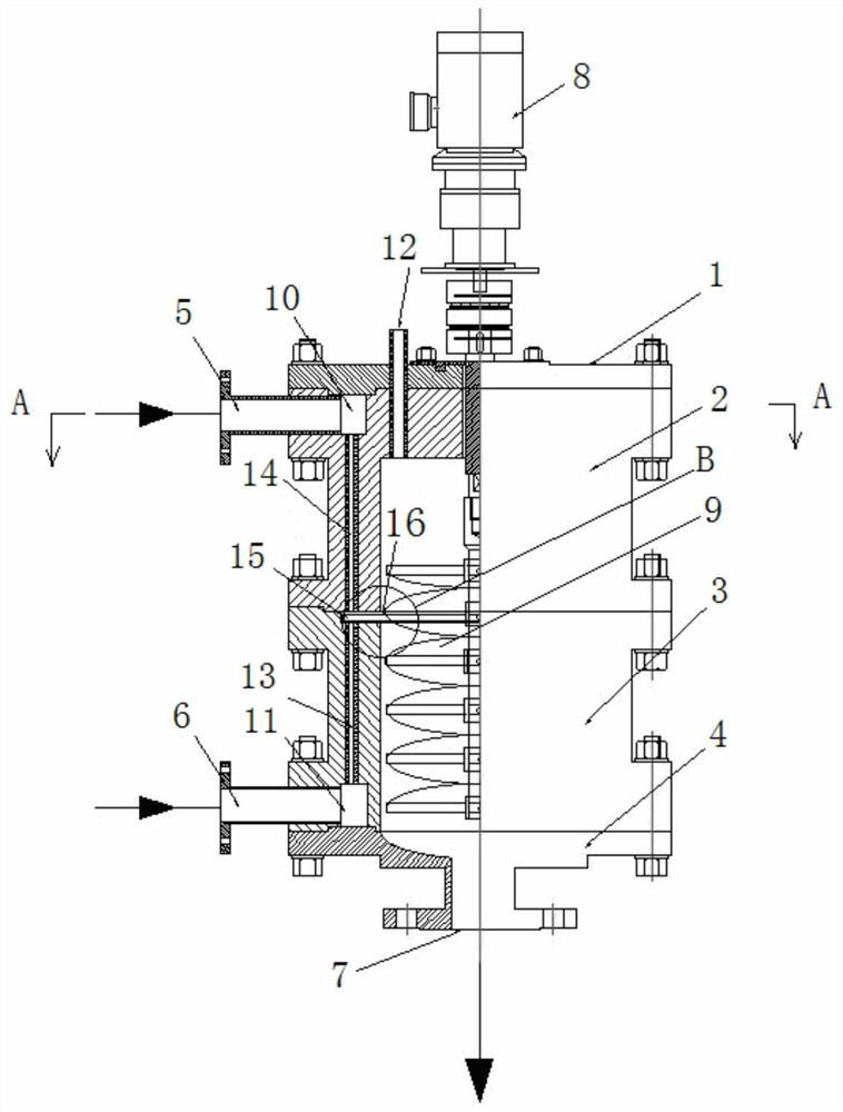
[0066] The above-mentioned continuous preparation of azo compounds is adopted, wherein the inner diameter of the nozzle used in the micro-collision flow stirring reactor 109 is 0.8mm, the nozzle is a single-hole structure, and the distance between the upper and lower nozzles is 15mm; the number of scrapers 16 is n=3, a =15mm, b=20mm, c=4mm; R=100mm, r=360 / min.

[0067] Continuous preparation of disperse red S-5BL compound:

[0068]

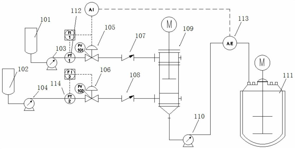
[0069] The temperature in the first storage tank 101 is 10°C, the concentration is 4.1% o-chloro-p-nitroaniline diazonium salt solution is sent into the collision flow stirring reaction through the first feed pump 103 through the first flow meter 112 and the first regulating valve 105 In the device 109, the N,N-diacetoxyethyl m-acetaniline solution with a temperature of 10°C and a concentration of 7.6% in the second storage tank 102 is passed through the second flowmeter 114 and the second The regulating valve 106 is sent into the collision flow...

Embodiment 1

[0070] Comparative Example One: Batch Synthesis of Disperse Red S-5BL Compound

[0071] Slowly add the solution of o-chloro-p-nitroaniline diazonium salt with a concentration of 4.1% at a temperature of 10°C to a stirred tank containing a solution of N,N-diacetoxyethyl m-acetamidoaniline with a concentration of 7.6%, and control the temperature to react at 10°C After the addition, the stirring was continued for 2 h, filtered and washed with water to obtain the dye red S-5BL compound, the chromatographic content of the main compound was 88.5%, and the yield was 93.7%.

Embodiment 2

[0072] Embodiment two prepares Disperse Yellow 211 compound

[0073]

[0074] Using the micro-collision flow stirring reactor of Example 1, the temperature in the first storage tank 101 is 12° C., and the concentration of 4.77% o-nitro-p-chloroaniline diazonium salt solution is passed through the first flowmeter 112 through the first feed pump 103. and the first regulator valve 105 into the collision flow stirring reactor 109, the temperature in the second storage tank 102 is 18 ℃, the N-ethyl-3-cyano group-4-methyl-6-hydroxyl group of concentration 4.92% - The 2-pyridone solution is sent into the collision flow stirring reactor 109 through the second flow meter 114 and the second regulating valve 106 through the second feeding pump 104, and the two-phase volume flow rate is 200 L / h, and the two materials After the collision and mixing reaction in the collision flow stirring reactor 109, the generated material is sent to the slurry tank 111 through the discharge pump 110, w...


PUM


Abstract

The invention relates to the field of mixing devices in the chemical industry, in particular to a device and method for continuously preparing azo compound. After the diazonium salt solution in a first storage tank 101 and the coupling component solution in a second storage tank 102 continuously collide, mix and react in an impinging stream stirring reactor 109, the generated material is conveyedinto a slurry tank 111 under the action of a discharge pump 110, and the azo compound is obtained. The device is compact in overall structure and small in occupied area, can be used for chemical unitoperation of extraction and rapid mixing reaction, is particularly suitable for reaction for producing high-viscosity materials after mixing reaction, and facilitates continuous operation. According to the method disclosed by the invention, a micro impinging stream technology is combined with a stirring reactor so that mass transfer is enhanced, the blockage problem is effectively prevented, automatic control is conveniently realized, the reaction efficiency and the product yield are improved, and continuous synthesis of the azo compound is realized.

Description

technical field [0001] The invention relates to the field of mixing devices in the chemical industry, in particular to a device and method for continuously preparing azo compounds. Background technique [0002] Impinging stream technology is a relatively new engineering technology, which was first proposed by Belarusian scientist Elperin in 1961. Improve the mixing performance to achieve the purpose of enhancing heat transfer and mass transfer. At present, impinging flow technology has been widely used in various unit operations such as drying, absorption, extraction, mixing, heat transfer, crystallization, and combustion. [0003] In recent years, the research on microchannel reaction at home and abroad has gradually deepened, and various forms of impinging flow reactors such as immersion type and external circulation have been developed. However, there is no report on the application of the industrially implemented impinging stream technology to the synthesis of high-vis...

Claims


Application Information

Patent Timeline
IPC IPC(8): B01J19/26B01J19/18B01J4/00
CPCB01J19/26B01J19/0093B01J19/0053B01J19/18B01J4/008B01J2204/002
Inventor 杨林涛鄢冬茂胥维昌刘东刘冰边策周川王珂贾志远刘嵩
Owner SHENYANG RES INST OF CHEM IND
Learn More