High-pressure-resistant stainless steel pipe full-automatic production line

A stainless steel tube, fully automatic technology, applied in the direction of grinding feed movement, clamping, support, etc., can solve the problems of stainless steel tube inaccurate movement, automatic fixation, and reduced processing efficiency, so as to achieve easy picking, Easy to take and improve processing efficiency

Active Publication Date: 2021-01-05
江西康腾卫浴有限公司
View PDF6 Cites 4 Cited by
  • Summary
  • Abstract
  • Description
  • Claims
  • Application Information

AI Technical Summary

Problems solved by technology

[0005] The purpose of the present invention is to provide a full-automatic production line for high-pressure stainless steel pipes, to solve the problem that the stainless steel pipes in the prior art proposed in the background technology are often driven by conveyor belts when they are cut and transported to the cutting position, and the stainless steel pipes are in the transmission process. It cannot be fixed in the middle, which will cause the stainless steel pipe to not move accurately to the grinding position, and cannot be fixed automatically. It needs to be manually disassembled and fixed by the staff, which is more troublesome. The automation of the entire cutting and grinding process is low, which reduces the processing efficiency.
[0008] When working, the stainless steel pipes in the prior art are often driven by conveyor belts when they are cut and transported to the cutting position, but the stainless steel pipes cannot be fixed during the transmission process, which will cause the stainless steel pipes to not move accurately to the grinding position, and cannot be automatically fixed , requires manual operation by the staff to disassemble and fix, which is more troublesome. The automation of the entire cutting and grinding process is low, which reduces the 
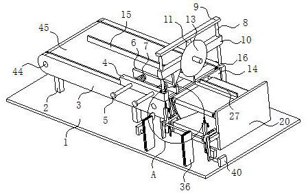
processing efficiency. The above-mentioned automatic production line for high-pressure stainless steel pipes places the stainless steel pipes that need to be cut on the transmission mechanism. , so that it is between the baffle and the splint, the transmission mechanism will drive the front end of the stainless steel tube to the position where it fits the rear wall of the fourth mounting plate, and at the same time, the magnetic suction cup will suck the stainless steel tube so that it will not move again, and then drive The mechanism stops working, start the first electric cylinder to extend downward, the first electric cylinder will drive the first slider to slide downward, and the first slider will drive the triangular slider, cutting blade and pressure plate to move downward synchronously, when When the inclined surface of the triangular slider touches the splint, the inclined surface of the triangular slider will act on the side wall of the splint to move the splint to the middle position of the transmission mechanism, and the splint will drive the stainless steel tube to move to the middle position. When the stainless steel tube moves to the middle position, the triangular When the slider continues to move downward, it will slide in the second chute and compress the first gas spring at the same time. The cutting blade moves downward to cut the stainless steel pipe. After the cutting is completed, the first slider just squeezes to the pressure sensor switch , the 
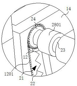
pressure sensor switch starts the opening function after receiving the pressure, the pressure sensor switch controls the rotation of the double-axis motor, the double-axis motor drives the gear to rotate, and the gear moves in the arc-shaped chute under the action of the teeth of the arc-shaped rack. The synchronous third rotating shaft rotates under the rotation drive of the double-axis motor. The rotation of the third rotating shaft will drive the first transmission belt to rotate. When the gear rotates to the bottom end of the arc-shaped chute, the first transmission belt will drive the stainless steel pipe to move to L-shaped Accept the position of the top surface of the bottom of the receiving plate, and then turn the rotating shaft to drive the fourth rotating shaft and the L-shaped receiving plate to rotate. The L-shaped receiving plate will drive the stainless steel tube to rotate together to make it detached from the magnetic suction cup, and then the first electric cylinder drives the first slider and The pressure plates move upwards together, the first slider is far away from the pressure sensing switch, the pressure sensing switch loses pressure and turns off the double-axis motor, and the gear returns to the initial position against the movement track under the action of the second return spring, so that the magnetic chuck is in the first position. Reset under the reset action of a 
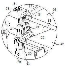
transmission belt. After the next work, the stainless steel pipes that have been cut are automatically transferred without manual operation, which is convenient for processing. When the L-shaped receiving plate continues to rotate, the L-shaped receiving plate rotates to a certain angle. The third slide bar will be in contact with the arc-shaped slide rail. Under the action of the arc-shaped slide rail, the third slide bar will drive the fixed bar to slide in the third chute and compress the second gas spring at the same time. When the L-shaped receiving plate rotates ° At the same time, the fixed rod moves to the bottom position and fixes the stainless steel tube at the same time, so that the transferred stainless steel tube is transferred to the belt grinding station, and it is automatically fixed, and then the grinding device is started to grind the cutting positions of the two ends of the stainless steel tube. After the grinding is completed, the L-shaped receiving plate rotates back to the initial position, and the staff can take out the polished stainless steel tube. Through the setting of the above structure, the cut stainless steel tube can be accurately moved to the grinding position, and the stainless steel tube can be automatically adjusted at the same time. Fixing allows the staff to take it easily and improves the processing efficiency

Method used


Image

  • High-pressure-resistant stainless steel pipe full-automatic production line
  • High-pressure-resistant stainless steel pipe full-automatic production line
  • High-pressure-resistant stainless steel pipe full-automatic production line

Examples


Embodiment Construction

[0030] The following will clearly and completely describe the technical solutions in the embodiments of the present invention with reference to the accompanying drawings in the embodiments of the present invention. Obviously, the described embodiments are only some, not all, embodiments of the present invention. Based on the embodiments of the present invention, all other embodiments obtained by persons of ordinary skill in the art without creative efforts fall within the protection scope of the present invention.

[0031] see Figure 1-9 , the present invention provides a technical solution: a fully automatic production line for high-pressure stainless steel pipes, including a bottom plate 1, two sets of support columns are fixedly connected to the top of the bottom plate 1, and the two sets of support columns each include two support rods 2, The tops of the two groups of support columns are fixedly connected with a first mounting plate 3, a transmission mechanism is arranged...


PUM


Abstract

The invention discloses a high-pressure-resistant stainless steel pipe full-automatic production line in the technical field of stainless steel pipe production. The high-pressure-resistant stainless steel pipe full-automatic production line comprises a bottom plate, two sets of supporting columns are fixedly connected to the top of the bottom plate, each supporting column comprises two supportingrods, first mounting plates are fixedly connected to the tops of the two sets of supporting columns, a transmission mechanism is arranged between the two first mounting plates, a grinding device is arranged in front of the top of the bottom plate, and a grinding positioning mechanism is arranged at the top of the bottom plate; and the polishing positioning mechanism comprises a second mounting plate fixedly connected to the top of the first mounting plate, and first sliding rods which are symmetrically arranged are slidably connected to the left side wall and the right side wall of the secondmounting plate located on the right side. And through the arrangement of the grinding positioning mechanism, the cut stainless steel pipe can accurately move to the grinding position, meanwhile, the stainless steel pipe can be automatically fixed, a worker can easily take the stainless steel pipe, and the machining efficiency is improved.

Description

technical field [0001] The invention relates to the technical field of stainless steel pipe production, in particular to a fully automatic production line for high-pressure stainless steel pipes. Background technique [0002] Stainless steel pipe is a hollow long round steel material, which is widely used in petroleum, chemical, medical, food, light industry, mechanical instrumentation and other industrial pipelines and mechanical structural components. At the same time, it is light in weight, so it is also widely used in the manufacture of mechanical parts and engineering structures. It is also commonly used as furniture and kitchen utensils. In the process of stainless steel pipe processing, the cutting position of the stainless steel pipe needs to be polished after cutting the stainless steel pipe. [0003] In the prior art, the stainless steel pipe is often driven by a conveyor belt when it is cut and transported to the cutting position, but the stainless steel pipe can...

Claims


Application Information

Patent Timeline
Patent Type & Authority Applications(China)
IPC IPC(8): B23P23/04B23Q3/154B23Q7/00B24B9/04B24B41/00B24B41/06
CPCB23P23/04B23Q3/154B23Q7/00B24B9/04B24B41/005B24B41/06
Inventor 任彦成
Owner 江西康腾卫浴有限公司
Why Eureka
Try Eureka