
Unmanned aerial vehicle attitude control system with variable-angle fan blade control surfaces

A technology for controlling the system and aircraft attitude, which is applied in aircraft control, aircraft parts, and weight reduction, and can solve problems such as complex structure, weak adjustment ability, and high output torque requirements of the steering gear.

Pending Publication Date: 2021-01-05
百奥创新(天津)科技有限公司
View PDF0 Cites 0 Cited by
  • Summary
  • Abstract
  • Description
  • Claims
  • Application Information

AI Technical Summary

Problems solved by technology

[0007] Aiming at the deficiencies in the prior art, the present invention provides a UAV attitude control system with a variable-angle fan blade rudder surface, which solves the following problems in the control mode of the existing dual-rotor UAV: ​​(1) pitch adjustment, The structure is complex and bulky, and the cost of production and maintenance is high; (2) The vector thrust adjustment requires a large output torque of the steering gear, and the response is poor, and the slight deflection of the steering gear will produce obvious pitch control effects, making the vector control The stability of the aircraft is poor, and the aircraft is prone to jitter; (3) the adjustment of the slipstream rudder, the adjustment ability is weak, and a large rudder surface is required to produce sufficient control force, resulting in an increase in the windward surface and the problem of being easily disturbed by the airflow

Method used


Image

  • Unmanned aerial vehicle attitude control system with variable-angle fan blade control surfaces
  • Unmanned aerial vehicle attitude control system with variable-angle fan blade control surfaces
  • Unmanned aerial vehicle attitude control system with variable-angle fan blade control surfaces

Examples


Embodiment Construction

[0027] The following will clearly and completely describe the technical solutions in the embodiments of the present invention with reference to the accompanying drawings in the embodiments of the present invention. Obviously, the described embodiments are only some, not all, embodiments of the present invention. Based on the embodiments of the present invention, all other embodiments obtained by persons of ordinary skill in the art without making creative efforts belong to the protection scope of the present invention.

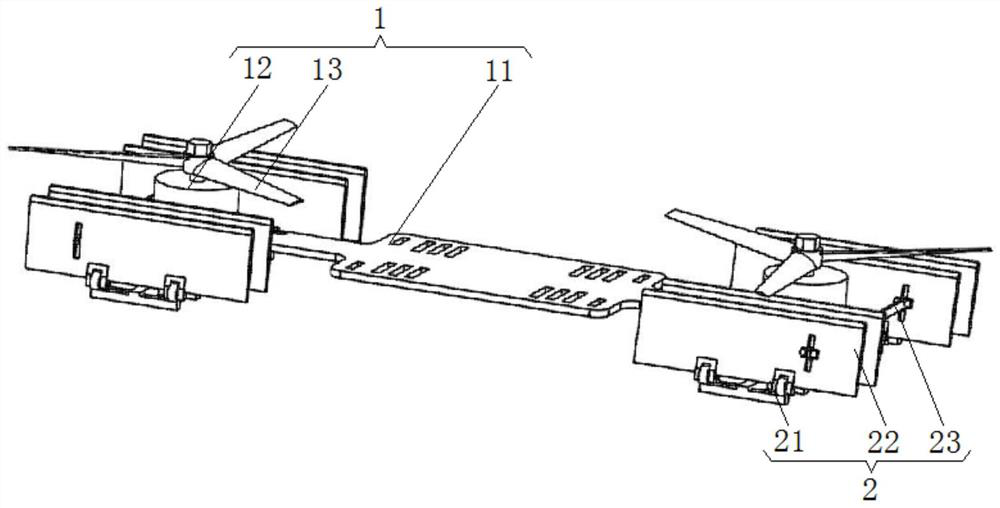
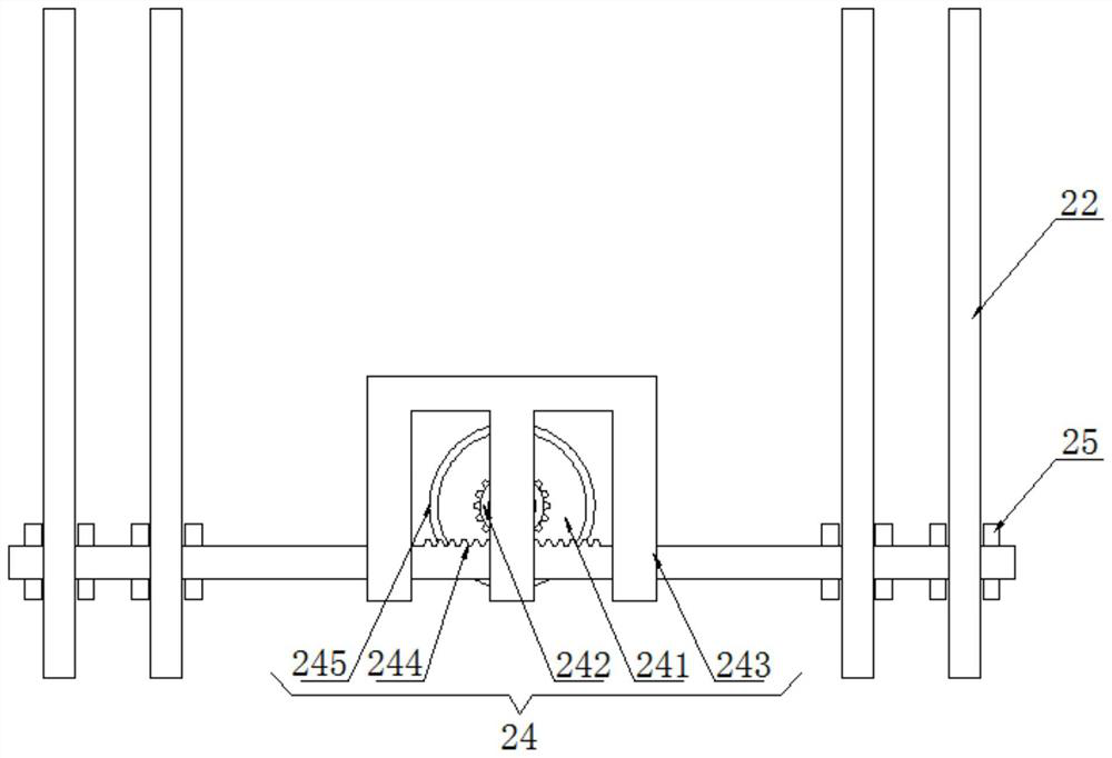
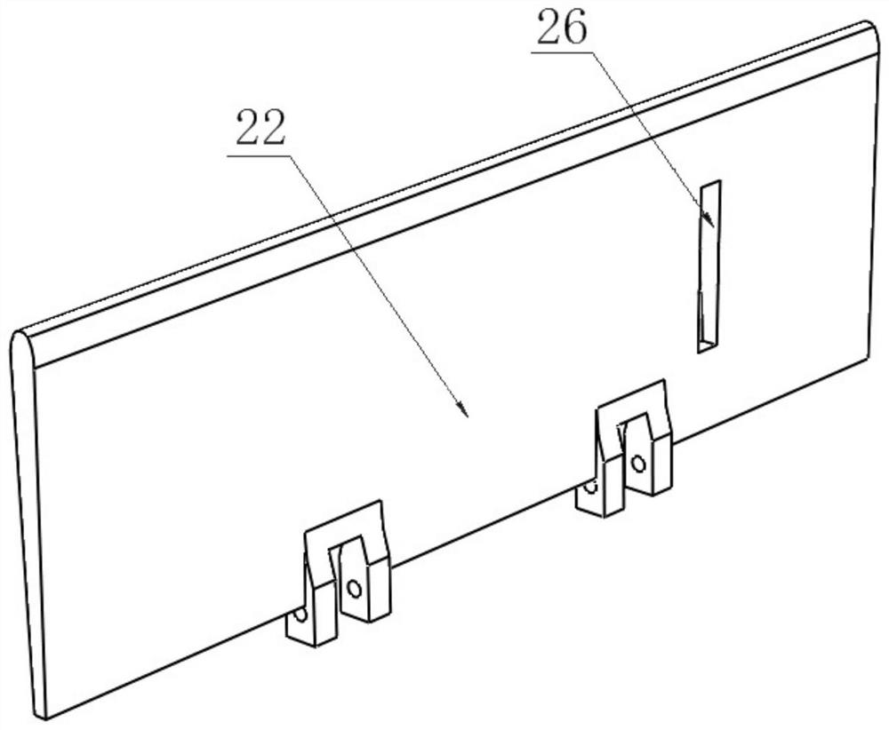
[0028] see Figure 1-3 , the present invention provides a technical solution: a UAV attitude control system with a variable-angle blade rudder surface, including a main body 1 and rudder surface systems 2 arranged on both sides thereof, the main body 1 includes a carbon fiber base 11, a brushless The motor 12 and the rotor 13, the brushless motor 12 and the rotor 13 are all provided with two groups, and the brushless motor 12 is symmetrically fixedly connected...


PUM


Abstract

The invention discloses an unmanned aerial vehicle attitude control system with variable-angle fan blade control surfaces. The control system comprises a main body and control surface systems arrangedon two sides of the main body, the main body comprises a carbon fiber base, a brushless motor and rotors, each control surface system comprises a bracket, a control surface group, a connecting rod and a steering engine mechanism, and the invention relates to the technical field of aircraft attitude control. Compared with variable pitch adjustment, the unmanned aerial vehicle attitude control system with the variable-angle fan blade control surface is simple in structure, small in axial size and low in production and maintenance difficulty and cost; compared with vector adjustment, the controlsystem has the characteristics that the stability and rapidity are better, the requirement for the output torque of a steering engine is not high, in other words, control can be achieved through thesmall steering engine, and the weight is reduced; compared with sliding flow rudder adjustment, the control system has the advantages that the adjustment effect is good, the windward side is small, and the anti-interference capacity is higher; and efficient and stable control of the fixed double rotors is realized, the flexibility is higher, the stability is better, and the control system is moresuitable for take-off and landing control of VTOL and STOVL aircrafts.

Description

technical field [0001] The invention relates to the technical field of aircraft attitude control, in particular to an unmanned aerial vehicle attitude control system with variable-angle blade rudder surfaces. Background technique [0002] VTOL and STOVL aircraft are an important research topic in the modern aviation industry. At present, the most used solutions in the field of unmanned aerial vehicles are tailseat vertical take-off and landing, tilt rotor aircraft and compound wing vertical take-off and landing UAVs. The current mainstream solutions The aerodynamic layout of quadrotors is mostly used during vertical take-off and landing, which means that the weightlessness, volume and air resistance during level flight are increased. Therefore, it is necessary to develop dual-rotor UAVs. To solve such problems, the layout of the lift fan integrated into the wing can be adopted to reduce the air resistance during level flight. Since VTOL and STOVL unmanned aerial vehicles ha...

Claims


Application Information

Patent Timeline
Patent Type & Authority Applications(China)
IPC IPC(8): B64C9/00
CPCB64C9/00Y02T50/40
Inventor 周剑锋张益鑫赵正
Owner 百奥创新(天津)科技有限公司
Learn More