
Electric variable-pitch turboprop engine

A turboprop and engine technology, applied in the direction of motor-driven engines, propellers, machines/engines, etc., can solve the problems that affect the acceleration and deceleration performance of propeller aircraft, the load inertia cannot be changed quickly, and the hydraulic pitch variable mechanism is bulky, etc., to achieve Quickly adjust the blade angle, simple structure, and less system parts

Active Publication Date: 2021-01-05
上海尚实航空发动机股份有限公司
View PDF7 Cites 3 Cited by
  • Summary
  • Abstract
  • Description
  • Claims
  • Application Information

AI Technical Summary

Problems solved by technology

[0008] (1) Due to insufficient actuation performance and large load inertia, it is impossible to quickly change the blade angle and match the torque required to maintain the propeller, which seriously affects the acceleration and deceleration performance of the propeller aircraft;
[0009] (2) Due to the need to provide high-pressure hydraulic oil to the high-speed propeller for a long time, the sealing ring used for dynamic sealing is prone to failure and oil leakage, resulting in the risk that the propeller cannot achieve pitch change;
[0010] (3) The high-speed dynamic seal cannot provide high hydraulic pressure. In order to achieve the required variable pitch force, the volume of the hydraulic variable pitch mechanism is very large

Method used


Image

  • Electric variable-pitch turboprop engine
  • Electric variable-pitch turboprop engine
  • Electric variable-pitch turboprop engine

Examples


Embodiment Construction

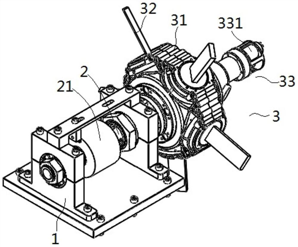
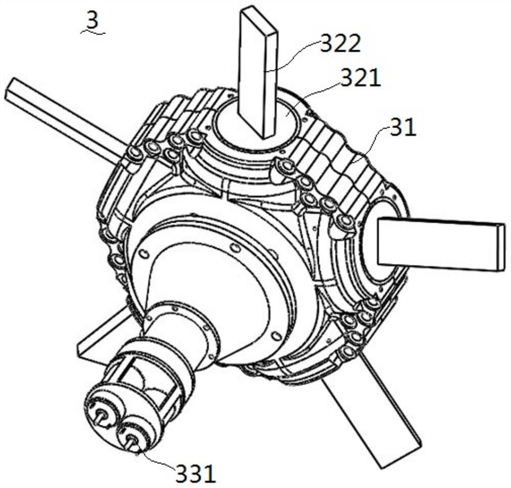
[0048] Specific embodiments of the electric pitch variable turboprop engine of the present invention: the electric pitch variable turboprop engine comprises a gas turbine engine, a speed reduction device and a propeller, and the basic principle of the turboprop engine is an existing mature technology, its working principle, structure, etc. It is easy to find on the browser, and this part of the structure has nothing to do with the improvement of the present invention. It is only necessary to know that the gas turbine engine can drive the propeller to rotate through the deceleration device, so that a pulling force is generated at the propeller to drive the body to move. Here is to save space , no more details. figure 1 Shown is the connection state diagram of the propeller 3 and the main shaft 2 in the prior art, as can be seen from the figure, one end of the propeller 3 is connected with the main shaft 2, and the other end is connected with the pitch-changing mechanism 33, and ...


PUM


Abstract

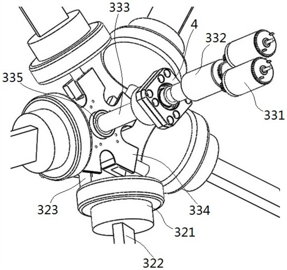
The invention relates to an electric variable-pitch turboprop engine. The variable-pitch propeller turboprop engine comprises a propeller, the propeller comprises a shell, blades and a variable pitchmechanism, the blades are rotationally assembled on the shell, each blade comprises a rotating disc, a vane and an eccentric driving lever, the vanes and the rotating discs are coaxial, a polygonal mounting cavity is formed among the rotating discs in the shell, and the variable pitch mechanism comprises a motor, a speed reducer, a shaft coupling, a lead screw and a driving disc, and further comprises a poking disc. The poking disc is installed on the lead screw through a lead screw nut, the lead screw is assembled on the shell in a rotating mode, the poking disc is in circumferential rotationstopping fit and axial sliding fit with the cavity wall of the polygonal mounting cavity through a rotation stopping face, the poking disc moves in the axial direction of the lead screw along with rotation of the lead screw, and U-shaped grooves are formed in the poking disc and correspond to the eccentric poking rods in a one-to-one mode. Each eccentric poking rod is inserted into the corresponding U-shaped groove, and when the poking disc moves along the axial direction of the lead screw, eccentric poking pins are pushed to rotate along the axis of the turntable through the U-shaped grooves. The engine has the advantages of quick response to change the blade angle, safety, stability and small size.

Description

technical field [0001] The present invention relates to electrically variable pitch turboprop engines. Background technique [0002] Turbine engine (Turbine engine, or often simply referred to as Turbine) is a form of engine that uses rotating parts to extract kinetic energy from fluid passing through it, and is a type of internal combustion engine. It is often used as an engine for aircraft and large ships or vehicles. [0003] According to fuel economy and actual use, it is divided into three structures: turbojet engine, turbofan engine and turboprop engine. [0004] The turbojet engine, referred to as the turbojet engine, is to directly eject the combusted gas and provide kinetic energy by the thrust of the ejected airflow. The advantage is that the high speed is particularly good, and the disadvantage is that the fuel economy is poor. Turbojet engines are mainly used in general fighter jets, bombers, drones, etc. [0005] Turbofan engine, referred to as turbofan engi...

Claims


Application Information

Patent Timeline
Patent Type & Authority Applications(China)
IPC IPC(8): B64C11/44B64D27/10B63H3/06B63H21/16F02C6/20
CPCB63H3/06B63H21/16B64C11/44B64D27/10F02C6/206
Inventor 邱国才韩广雷鲁玉泉王石柱
Owner 上海尚实航空发动机股份有限公司
Learn More