
A jacketed high-pressure hydrogen storage device for a hydrogen refueling station

A hydrogen storage device and jacket type technology, which is applied in the installation device of container structure, pressure vessel, fixed-capacity gas storage tank, etc., can solve the problems of increased susceptibility to hydrogen embrittlement of materials, decreased fatigue resistance, and high manufacturing reliability. problems, to achieve the effects of easy guarantee of hardenability, suppression of fatigue expansion, and high manufacturing reliability

Active Publication Date: 2022-02-18
EAST CHINA UNIV OF SCI & TECH
View PDF4 Cites 0 Cited by
  • Summary
  • Abstract
  • Description
  • Claims
  • Application Information

AI Technical Summary

Problems solved by technology

[0003] However, during the long-term service in the high-pressure hydrogen environment, the durability of the hydrogen storage device will decrease due to the hydrogen embrittlement of the material, and the fatigue crack growth rate will be greatly accelerated, resulting in a significant decrease in its anti-fatigue failure performance. High, the susceptibility to hydrogen embrittlement of materials increases, and this problem is more prominent. Therefore, ensuring the durability of high-pressure hydrogen storage devices is a key issue to ensure the long-term safe and stable operation of hydrogen refueling stations
[0004] In the prior art, there are mainly two technical solutions to solve the problem of durability decline caused by hydrogen embrittlement of high-pressure hydrogen storage devices: one is a single-layer, large-wall-thick, non-welded pressure vessel made of low-alloy high-strength steel. The solution effectively reduces the stress level of the inner wall of the hydrogen storage device by increasing the wall thickness of the hydrogen storage device and self-reinforcement technology, thereby reducing the fatigue risk caused by hydrogen embrittlement of the hydrogen storage container. The advantage of this solution is that the manufacturing process is relatively simple, but its disadvantages are The effective volume ratio is very low, and the non-welded container with large wall thickness can only adopt single-sided heat treatment process. The excessive wall thickness of the container leads to poor hardenability of quenching heat treatment, and it is difficult to guarantee the material properties after heat treatment; the other is to use multi-layer concentric A multi-layer hydrogen storage device composed of cylindrical shells. In this solution, carbon fibers, steel strips or steel plates are used to wrap or wrap around the thin-walled container made of austenitic stainless steel. With the help of the low hydrogen embrittlement susceptibility of austenitic stainless steel itself To reduce the risk of hydrogen embrittlement fatigue of hydrogen storage devices, this scheme has the advantages of good hydrogen embrittlement resistance and large effective volume, but its disadvantages are that the manufacturing process of multilayer hydrogen storage devices is complicated, the welds are many and dense, and the welding quality control is difficult , long production cycle and high cost
It can be seen that the existing technology still fails to solve the requirements of the development of the fuel cell industry that the high-pressure hydrogen storage device has a large effective volume, good resistance to hydrogen embrittlement, high manufacturing reliability and low cost.

Method used


Image

  • A jacketed high-pressure hydrogen storage device for a hydrogen refueling station
  • A jacketed high-pressure hydrogen storage device for a hydrogen refueling station
  • A jacketed high-pressure hydrogen storage device for a hydrogen refueling station

Examples


Embodiment Construction

[0037] Below in conjunction with accompanying drawing, the present invention will be further described.

[0038] The realization process of the inventive method is as follows:

[0039] A jacketed high-pressure hydrogen storage device for a hydrogen refueling station:

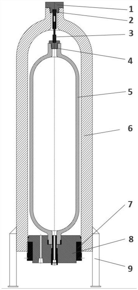
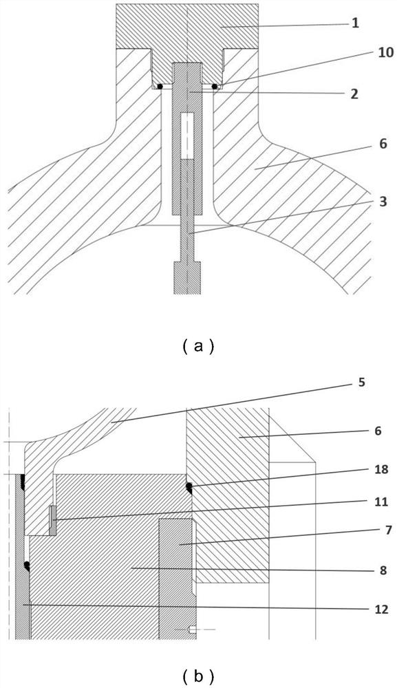
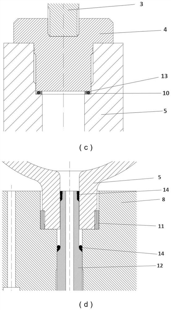
[0040] Assemble the inner container assembly, connect the upper end cap 4 of the inner container with the connecting pin 3 through threads, install the O-ring 10 and the sealing retaining ring 13 of the inner container on the platform in the bottle mouth of the upper end of the inner cylinder body 5, and put the upper end cap 4 of the inner container It is threadedly connected with the inner cylinder body 5, and the lower end cover 11 of the inner container is connected with the inner cylinder body 5 through threaded connections to complete the assembly of the inner container assembly.

[0041] Assemble the outer container assembly, connect the upper end cap 1 of the outer container with the connecting sleeve 2...


PUM


Abstract

The invention discloses a jacketed high-pressure hydrogen storage device for a hydrogen refueling station. The device adopts a non-welded double-layer cylinder structure, the inner container is a large-volume seamless gas cylinder, and the outer container is a large-volume seamless gas cylinder with one side open. For seamed gas cylinders, one side of the inner and outer containers is supported by the support rod, and the other side is supported by the end plug plate to realize the support of the inner container in the outer container. The inner container is filled with high-pressure hydrogen, and the outer container is filled with high-pressure nitrogen as a balance gas. The stress level of the inner container is adjusted by balancing the gas pressure, and the crack growth driving force of the inner container is reduced. The inner container can be made of austenitic stainless steel with good hydrogen compatibility, and the outer container can be made of high-strength steel to withstand high-pressure nitrogen. The invention effectively solves the problem of hydrogen embrittlement of the current single-layer hydrogen storage container material, and also overcomes the complex manufacturing process of the existing multi-layer high-pressure hydrogen storage device, many and dense welds, difficult welding quality control, long production cycle and high cost Shortcomings.

Description

technical field [0001] The invention relates to the field of new energy storage and transportation, and relates to a jacketed high-pressure hydrogen storage device for a hydrogen refueling station, in particular to a fixed storage device suitable for high-pressure hydrogen. Background technique [0002] In the hydrogen fuel cell vehicle industry, hydrogen refueling stations need to compress hydrogen to a pressure of 45MPa-99MPa and store it in a high-pressure hydrogen storage device. The high-pressure hydrogen storage device is a steel single-layer or multi-layer cylindrical shell pressure vessel. According to the refueling process requirements of hydrogen refueling stations on the market, the high-pressure hydrogen storage device of the hydrogen refueling station needs to withstand fatigue loads with a fluctuation range of about 20MPa about 100,000 times within its design life. Once the hydrogen storage device suddenly fails due to fatigue, There will be a hydrogen explosio...

Claims


Application Information

Patent Timeline
Patent Type & Authority Patents(China)
IPC IPC(8): F17C1/02F17C1/14F17C13/06
CPCF17C1/02F17C1/14F17C13/002F17C13/06F17C2201/0109F17C2201/032F17C2203/011F17C2203/0612F17C2203/0639F17C2203/0643F17C2203/0646F17C2203/068F17C2205/03F17C2221/012F17C2223/0123F17C2225/0123Y02E60/32
Inventor 黄淞惠虎
Owner EAST CHINA UNIV OF SCI & TECH
Learn More