Integrated two-stage heating efficient energy-saving heat pipe steam generator
A steam generator and two-stage heating technology, which is applied in steam generation, steam generation method using heat carrier, steam generation method, etc., can solve the problems of low heat transfer efficiency and low heat utilization rate of flue gas, and achieve increased exchange rate. Heat speed and evaporation speed, avoid the reduction of heat utilization rate, and improve the effect of waste heat utilization
- Summary
- Abstract
- Description
- Claims
- Application Information
AI Technical Summary
Problems solved by technology
Method used
Image

Examples
Embodiment 1
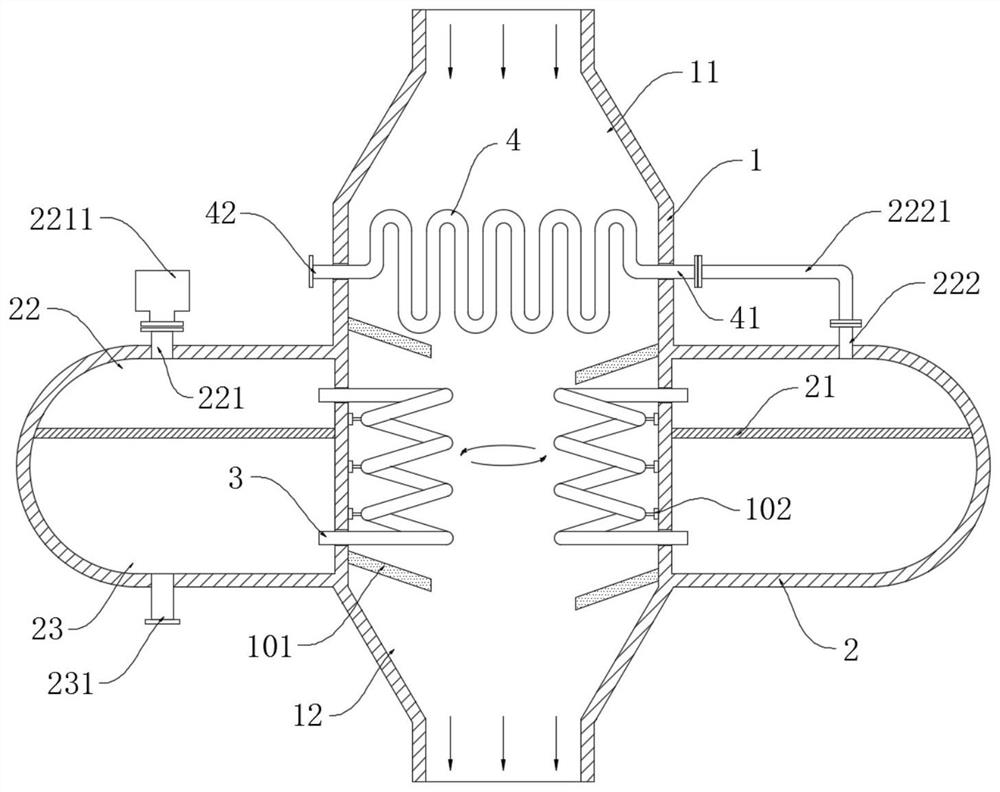
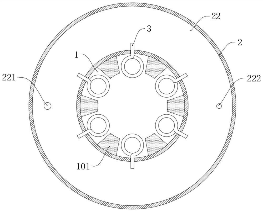
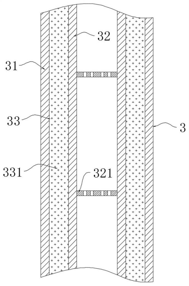
[0039] refer to Figure 1-3 , an integrated two-stage temperature-raising high-efficiency energy-saving heat pipe steam generator, including a flue gas pipe 1, the upper end and lower end of the flue gas pipe 1 are respectively installed with an inlet connecting pipe 11 and an outlet connecting pipe 12, and the outer wall of the flue gas pipe 1 is surrounded by A steam tank 2 is installed, and a water inlet pipe 231 is installed at the lower end of the steam tank 2. A primary exhaust pipe 222 and a safety pipe 221 are installed above the steam tank 2. A safety valve 2211 is installed on the safety pipe 221. A steam tank 2 is installed with The partition plate 21, the upper and lower layers of the partition plate 21 are the steam chamber 22 and the water storage chamber 23 respectively, and a plurality of holders 102 are symmetrically installed on the inner wall of the flue gas pipe 1, and a plurality of spirals are respectively installed on the plurality of holders. The heat pip...
Embodiment 2
[0049] refer to Figure 4 , an integrated two-stage temperature-raising high-efficiency energy-saving heat pipe steam generator, which is basically the same as Embodiment 1, the difference is:
[0050] A plurality of steam tanks 2 are equidistantly installed on the outer wall of the flue gas pipe 1, and the air inlet 41 of the secondary heating heat pipe 4 extends to the outside of the flue gas pipe 1 and is equipped with a collecting pipe 5. A branch pipe 51, and a plurality of branch pipes 51 are respectively connected to a plurality of primary exhaust pipes 222, and each branch pipe 51 is equipped with a solenoid valve 511, and the water inlet pipe 231 of the upper floor is connected with the safety pipe 221 of the lower floor;
[0051] Multiple steam tanks 2 can evaporate water step by step, increase the heat utilization rate of high-temperature flue gas, and can heat water step by step to a high-temperature critical state in low-temperature flue gas, and staged heating ca...
Embodiment 3
[0055] refer to Figure 5-7 , an integrated two-stage temperature-raising high-efficiency energy-saving heat pipe steam generator, which is basically the same as Embodiment 1, the difference is:
[0056] A pneumatic liquid pump 6 is installed on the inner wall of the lower end of the flue gas pipe 1. The pneumatic liquid pump 6 includes an annular pump casing 61 installed on the inner wall of the flue gas pipe 1. The inner ring of the annular pump casing 61 is sealed and rotated with an inner ring wall ring 62. Airflow fan blades 621 are installed on the inner wall of the inner ring wall ring 62, and a plurality of pump blades 622 are installed in a circular equidistant manner on the outer wall of the inner ring wall ring 62, and the lower end of the water inlet pipe 231 extends into the annular pump casing 61. 61 is installed with a suction pipe 63, and the end of the suction pipe 63 away from the annular pump casing 61 extends to the outside of the flue gas pipe 1;
[0057]...
PUM
 Abstract
Description
Claims
Application Information
 - R&D
- Intellectual Property
- Life Sciences
- Materials
- Tech Scout
- Unparalleled Data Quality
- Higher Quality Content
- 60% Fewer Hallucinations
Browse by: Latest US Patents, China's latest patents, Technical Efficacy Thesaurus, Application Domain, Technology Topic, Popular Technical Reports.
© 2025 PatSnap. All rights reserved.Legal|Privacy policy|Modern Slavery Act Transparency Statement|Sitemap|About US| Contact US: help@patsnap.com