Efficient cooling device for calcium carbide waste heat recovery

A waste heat recovery and cooling device technology, which is applied in the field of cooling devices and high-efficiency cooling devices, can solve problems such as increased production costs, difficulty in utilization, and high viscosity, and achieve the effects of enhanced heat transfer performance, increased turbulence, and improved PEC value

Active Publication Date: 2021-01-05
XI AN JIAOTONG UNIV
View PDF6 Cites 0 Cited by
  • Summary
  • Abstract
  • Description
  • Claims
  • Application Information

AI Technical Summary

Problems solved by technology

Calcium carbide is mainly cooled naturally by placing it in a container made of cast iron. This method has the following defects. One is that high-grade heat energy is wasted in large quantities, and the other is that natural cooling will cause certain thermal pollution and environmental pollution. Dust pollution, the third is that due to its high temperature, it needs to be placed in a special factory building that has undergone refractory treatment, which reduces the turnover efficiency of the enterprise and increases the production cost
The main reasons for the waste of these high-grade heat energy are insufficient heat recovery means and low efficiency
Calcium carbide in the molten state is close to 2000°C, but has low thermal conductivity, high viscosity, and reacts with nitrogen and water, so it is difficult to use traditional methods

Method used


Image

  • Efficient cooling device for calcium carbide waste heat recovery
  • Efficient cooling device for calcium carbide waste heat recovery
  • Efficient cooling device for calcium carbide waste heat recovery

Examples


Embodiment Construction

[0039] In order to make the purpose, technical solutions and advantages of the embodiments of the present invention clearer, the technical solutions in the embodiments of the present invention will be clearly and completely described below in conjunction with the drawings in the embodiments of the present invention. Obviously, the described embodiments It is a part of embodiments of the present invention, but not all embodiments. The components of the embodiments of the invention generally described and illustrated in the figures herein may be arranged and designed in a variety of different configurations.

[0040] Accordingly, the following detailed description of the embodiments of the invention provided in the accompanying drawings is not intended to limit the scope of the claimed invention, but merely represents selected embodiments of the invention. Based on the embodiments of the present invention, all other embodiments obtained by persons of ordinary skill in the art wi...


PUM


Abstract

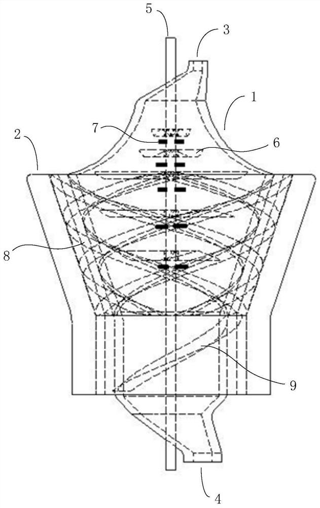
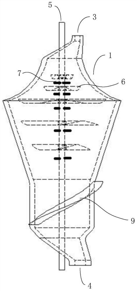
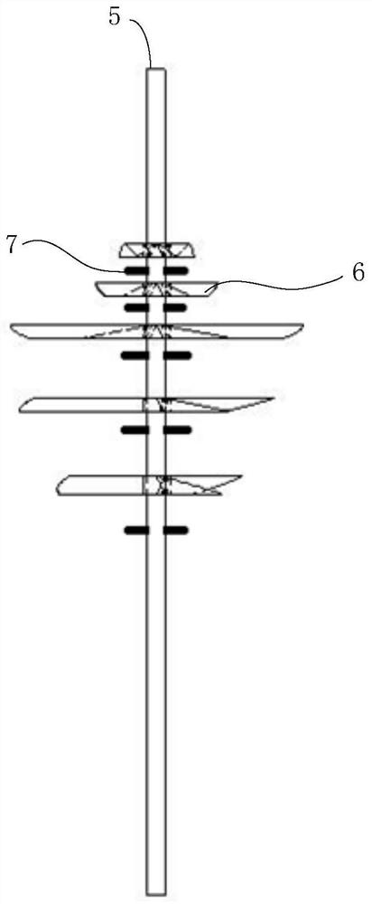
The invention discloses an efficient cooling device for calcium carbide waste heat recovery. An inner heat exchange barrel and an outer heat insulation barrel are arranged, an annular flow channel isarranged between the inner heat exchange barrel and the outer heat insulation barrel, the inner wall and the outer wall of the inner heat exchange barrel serve as main heat exchange interfaces, when calcium carbide is cooled, a fan blade array and a plurality of cooling water nozzles are arranged in the inner heat exchange barrel, and the cooling water nozzles spray cooling water in a main water pipe to the inner wall of the inner heat exchange barrel to exchange heat with calcium carbide in the annular flow channel; and the outer heat insulation barrel can rotate relative to the inner heat exchange barrel, through cooperation with a first scraper, calcium carbide drainage can be realized, and meanwhile, the outer wall surface of the inner heat exchange barrel can be cleaned. According tothe efficient cooling device, for a calcium carbide furnace with the magnitude of 48 MVA or below, molten calcium carbide which is just discharged from the furnace and is at the temperature of 2,000 DEG C can be cooled to about 1,400 DEG C within 30 minutes; and granulation of calcium carbide solids can be achieved at the outlet section, so that efficient production of the calcium carbide is achieved.

Description

【Technical field】 [0001] The invention belongs to the technical field of calcium carbide cooling, and relates to a cooling device, in particular to a high-efficiency cooling device for recovering calcium carbide waste heat. 【Background technique】 [0002] At present, the industrial production of calcium carbide is to use the arc heat generated by the three-phase carbon electrode of the calcium carbide furnace to cause the two raw materials of coke and lime to undergo a solid-phase melting chemical reaction to generate high-temperature molten calcium carbide at about 2000 °C. Calcium carbide is mainly cooled naturally by placing it in a container made of cast iron. This method has the following defects. One is that high-grade heat energy is wasted in large quantities, and the other is that natural cooling will cause certain thermal pollution and environmental pollution. Dust pollution, the third is that due to its high temperature, it needs to be placed in a special factory b...

Claims


Application Information

Patent Timeline
Patent Type & Authority Applications(China)
IPC IPC(8): F28D11/02F28F9/00F28F17/00F28G3/10B02C18/08
CPCB02C18/08F28D11/02F28F9/00F28F17/00F28G3/10
Inventor 车得福辛昊哲刘德文辛世纪詹舒童王泽刘虎
Owner XI AN JIAOTONG UNIV
Why Eureka
Try Eureka