
A non-penetrating electron beam welding seam structure and welding method

An electron beam welding, non-penetrating technology, which is applied in the direction of electron beam welding equipment, welding equipment, manufacturing tools, etc., can solve the problems of decreased quality of welding, gas cannot be discharged, and difficult processing, etc., so as to reduce assembly difficulty and eliminate Pore ​​defects, the effect of improving the technical level

Active Publication Date: 2022-04-12
HANGZHOU TURBINE POWER GRP
View PDF11 Cites 0 Cited by
  • Summary
  • Abstract
  • Description
  • Claims
  • Application Information

AI Technical Summary

Problems solved by technology

This kind of scheme adopts the method of repair welding to eliminate the defect, but the secondary welding seam is easy to ablate the main part of the part, and the spatter pollution produced at the same time is difficult to remove
Chinese patent CN110524101A adopts a comparative experiment method to find the most suitable welding parameters through testing. This solution is similar to the aforementioned technical solution and requires a lot of time and energy for testing, which is not applicable in actual mass production.
The above technical solution can be applied to non-penetrating electron beam welding and improved to penetrating type by improving the joint structure of the welding place and adding a process stop to prevent welding spatter. However, the structure is relatively complicated, the processing is difficult, and the defects discharged are not Without removal, it is not applicable in some application scenarios, especially the rotating ring parts. The same also includes the Chinese patent CN106570295A, which is equipped with a separate exhaust groove at the welding place. The structure is more complicated and the function of the mouth is single.
[0006] Chinese patents CN110508916A and CN111375880A both disclose a single-side seam structure arranged under the weld, which not only plays the role of assembly positioning, but also allows electron beam welding to pass through the weld to improve bottom defects. There are defects and the problem that the gas cannot be discharged, which leads to a decrease in the quality of the weld and produces a large number of small cracks, which seriously affects the life of the parts

Method used


Image

  • A non-penetrating electron beam welding seam structure and welding method
  • A non-penetrating electron beam welding seam structure and welding method
  • A non-penetrating electron beam welding seam structure and welding method

Examples


Embodiment Construction

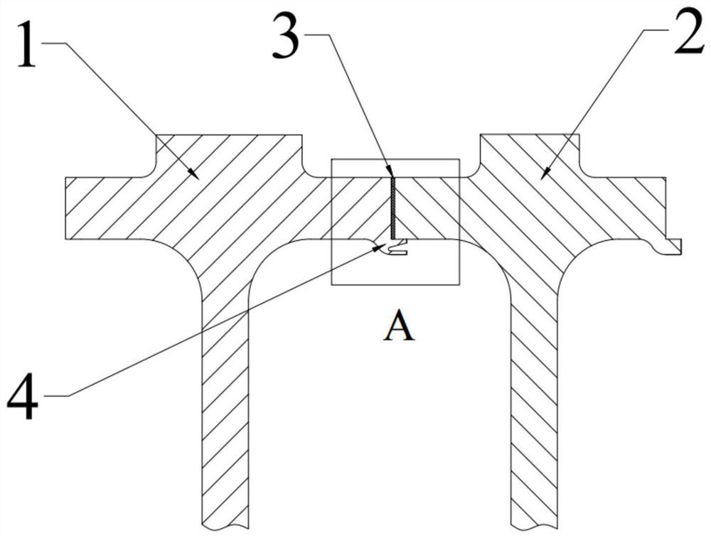
[0035] The following will be combined with Figure 1-2 , the present invention will be further described.

[0036] In the description of the present invention, it should be noted that the orientation or positional relationship indicated by the terms "under" and "below" are based on the attached figure 1 The orientation or positional relationship shown. Such terms are only for the convenience of describing the present invention and simplifying the description, rather than indicating or implying that the referred device or element must have a specific orientation, be constructed and operated in a specific orientation, and thus should not be construed as limiting the present invention.

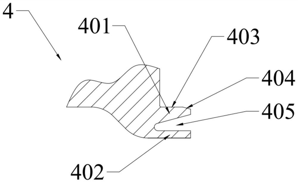
[0037] A non-penetrating electron beam welded spigot structure such as figure 1 As shown, it includes: the first welding part 1, the second welding part 2, the welding seam 3, and the notch 4. The weldments 1 and 2 are ring-shaped components, and the spigot 4 is located below the welding surfa...


PUM


Abstract

The invention discloses a non-penetrating electron beam welding spigot structure and welding method, comprising: a first weldment, a second weldment, a weld seam, and a spigot; the spigot is located below the welding surface of the first weldment, It is an inwardly bent flange structure; a weld seam is provided between the welding surfaces of the first weldment and the second weldment; the spigot protrudes outward from the lower surface of the first weldment, and the cross section is placed horizontally V-shaped structure, relying on the surface of the second weldment as the mating surface, the structure is a wedge-shaped groove; the advantages of the present invention are: through the designed wedge-shaped groove, the upper part forms an auxiliary positioning structure, which reduces the difficulty of assembly, and the groove body is conducive to eliminating air holes At the same time, the defects generated by welding are introduced into the seam, effectively blocking welding spatter, avoiding the influence of welding spatter on the use of parts, and reducing the occurrence of weld defects.

Description

technical field [0001] The invention relates to the field of welding technology, in particular to a non-penetrating electron beam welding notch structure and a welding method. Background technique [0002] Vacuum electron beam welding refers to a welding method that uses the heat energy generated by the converging high-speed electron flow to bombard the weld in a vacuum environment to fuse the metal to be welded. It has strong penetrating ability, fast welding speed, and small heat-affected zone. It has the characteristics of small welding stress, large depth-to-width ratio of weld seam, and good welding quality, which has advantages that are difficult to match with traditional welding methods. [0003] In the prior art, due to the fusion and recrystallization of the welded joint area, under normal circumstances, the joint has a better static load resistance than the base metal. However, due to various defects introduced during the welding process, the dynamic load resistanc...

Claims


Application Information

Patent Timeline
Patent Type & Authority Patents(China)
IPC IPC(8): B23K33/00B23K15/06
CPCB23K33/004B23K15/06B23K15/0046
Inventor 徐志明郑健生祝华云隋永枫王宏泽俞胤杰屠瑶谢健
Owner HANGZHOU TURBINE POWER GRP
Learn More