
Cabinet door plate machining system and material distributing and drilling line arrangement method thereof

A technology of processing system and layout method, which is applied in the direction of wood processing equipment, manufacturing tools, fixed drilling machines, etc., can solve the problems of not being able to supply cabinet door panels well, affecting the processing efficiency of cabinet door panels, and low processing and production efficiency. Improve drilling efficiency, ensure drilling quality, and ensure the effect of drilling operations

Inactive Publication Date: 2021-01-08
合肥志邦家居有限公司
View PDF4 Cites 1 Cited by
  • Summary
  • Abstract
  • Description
  • Claims
  • Application Information

AI Technical Summary

Problems solved by technology

[0003] During the processing and production process of the cabinet door panel, it needs to go through multiple processing processes, and the processing speeds between different processes are different, resulting in a poor connection between one processing process and the next processing process on the cabinet door panel, and to a certain extent It affects the processing efficiency of cabinet door panels, resulting in low processing and production efficiency, and cannot supply cabinet door panels very well.

Method used


Image

  • Cabinet door plate machining system and material distributing and drilling line arrangement method thereof
  • Cabinet door plate machining system and material distributing and drilling line arrangement method thereof
  • Cabinet door plate machining system and material distributing and drilling line arrangement method thereof

Examples


specific Embodiment 1

[0065] see figure 2 , when there are two even-numbered material-distributing drilling lines, the two material-distributing drilling lines are arranged semi-symmetrically.

[0066] In the specific layout, the length of the assembly line of one of the sub-drilling lines is lengthened by adding a roller transfer table, etc., and the output distance between the two adjacent plates to be processed on the two sub-drilling lines is staggered to ensure that the two The plate to be processed on the strip material drilling line can be smoothly transported to the next process.

[0067] For example, when two material-distributing drilling lines are arranged parallel to each other, a roller transfer platform can be set at both the feeding end and the discharging end of one of the material-distributing drilling lines. The roller transmission table set at the material end can change the conveying direction of the plate to be processed, so that the plate to be processed on each material dis...

specific Embodiment 2

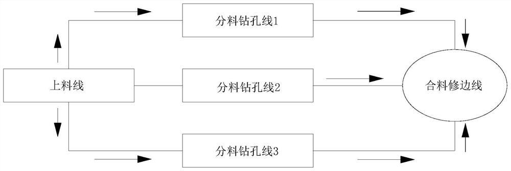
[0069] see image 3 , when the distribution drilling lines are an odd number of three, the three distribution drilling lines are symmetrically arranged.

[0070] In the specific layout, the three material distribution drilling lines are arranged parallel to each other and at equal intervals. The output spacing between two adjacent plates to be processed is staggered to ensure that the plates to be processed on the three distribution drilling lines can be smoothly conveyed to the next process.

[0071] For example, when three sub-material drilling lines are arranged parallel to each other, the middle sub-material drilling line is on the same line as the feeding line, and the other two sub-material drilling lines are symmetrical about the middle sub-material drilling line Arrangement, the roller transmission table is set at the feed end and the discharge end of the two-part material drilling line located on both sides of the middle material distribution drilling line, and the r...


PUM


Abstract

The invention discloses a cabinet door plate machining system and a material distributing and drilling line arrangement method thereof. The machining system comprises a feeding line, one or more material distributing and drilling lines, a material combining and trimming line and a handle mounting line which are arranged in sequence. The material distributing and drilling line arrangement method comprises the steps that all the material distributing and drilling lines are arranged in parallel in a tree diagram mode, and the output speed of to-be-machined plates at the discharging ends of all the material distributing and drilling lines and the output distance between every two adjacent to-be-machined plates on each material distributing and drilling line are coordinated. Through arrangementof the multiple material distributing and drilling lines, the drilling machining efficiency of the to-be-machined plates is improved; and meanwhile, the consumption rate of the to-be-machined plateson the feeding line by the material distributing and drilling lines can be increased, the working saturation of workers at the discharging ends of the material distributing and drilling lines is improved, and the output quantity of the to-be-machined plates at the discharging ends of the material distributing and drilling lines is guaranteed.

Description

technical field [0001] The invention relates to the technical field of cabinet door panel processing, in particular to a cabinet door panel processing system and a material distribution drilling line arrangement method thereof. Background technique [0002] With the continuous improvement of living standards, people have more and more demands for cabinets, cupboards, etc. in the kitchen, and their quality requirements are also getting higher and higher. [0003] During the processing and production process of the cabinet door panel, it needs to go through multiple processing processes, and the processing speeds between different processes are different, resulting in a poor connection between one processing process and the next processing process on the cabinet door panel, and to a certain extent It affects the processing efficiency of cabinet door panels, resulting in low processing and production efficiency, and cannot supply cabinet door panels well. In order to meet the ...

Claims


Application Information

Patent Timeline
IPC IPC(8): B27M3/18B27M1/08B27C3/04
CPCB27C3/04B27M1/08B27M3/18
Inventor 赵良才何允伟
Owner 合肥志邦家居有限公司
Learn More