Wind energy automobile power device

A technology for power devices and automobiles, applied in electric vehicles, wind power generation, wind engines, etc., can solve problems such as poor battery life, achieve the effects of prolonging the standby time, increasing practicability, and making full use of energy

Inactive Publication Date: 2021-01-08
苏州绿驰新能源汽车技术有限公司
View PDF0 Cites 0 Cited by
  • Summary
  • Abstract
  • Description
  • Claims
  • Application Information

AI Technical Summary

Problems solved by technology

[0003] Existing wind energy-powered vehicles have poor battery life during driving, and can only run according to the stored power of the battery of the electric vehicle itself. There is a need for a wind energy vehicle power plant that can generate electricity while driving

Method used


Image

  • Wind energy automobile power device
  • Wind energy automobile power device
  • Wind energy automobile power device

Examples


Embodiment 1

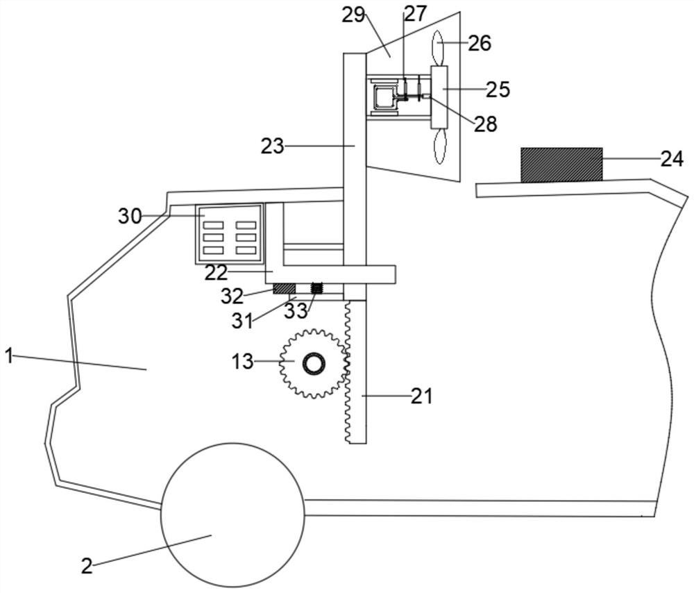
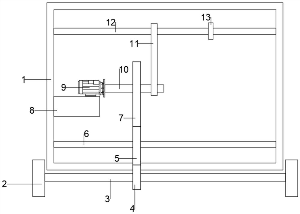
[0030] refer to Figure 1 ~ Figure 2, a wind energy vehicle power device, comprising a vehicle main body 1, a plurality of rolling wheels 2 are rollingly connected to the bottom of the vehicle main body 1, the middle part of the rolling wheels 2 is provided with a power mechanism to drive it to rotate, and the internal bearing of the vehicle main body 1 is connected to a transmission The shaft 12, the transmission shaft 12 and the power mechanism are linked, the upper shaft of the transmission shaft 12 is fixed with an adjustment gear 13, the right edge of the adjustment gear 13 is meshed with a spur rod 21, and the upper end bolt of the spur rod 21 is connected with a slide rod 23, The sliding rod 23 runs through the upper shell wall of the automobile main body 1, and the end bolt of the sliding rod 23 away from the straight gear rod 21 is connected with a wind power generating box 27. One end is rotatably connected with a rotating shaft 28, the rotating shaft 28 runs through...

Embodiment 2

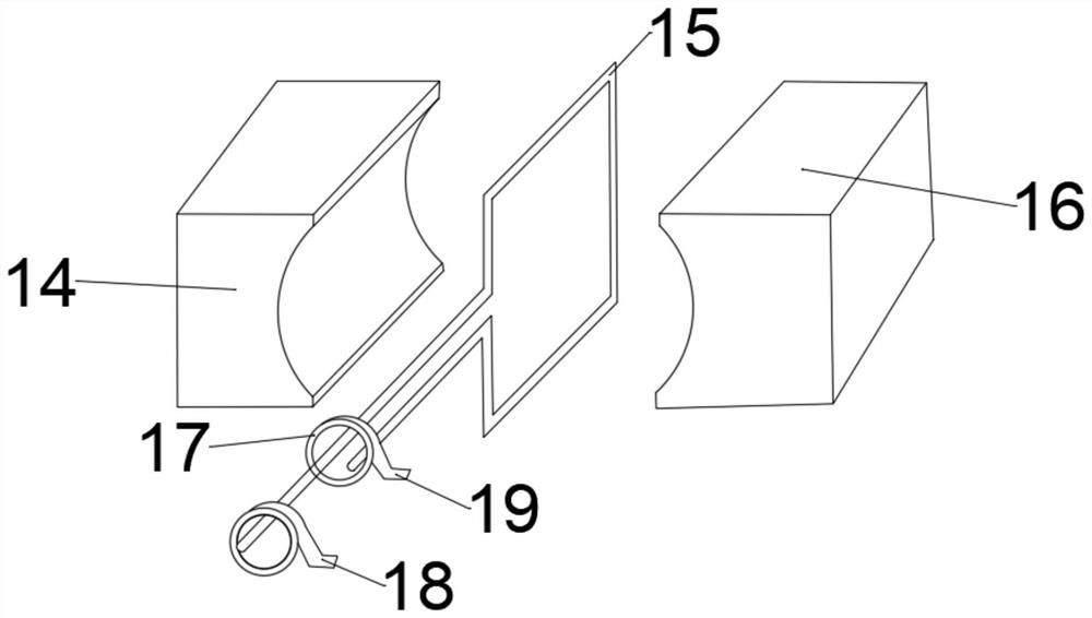
[0038] refer to Figure 3 ~ Figure 4 , a power device for a wind energy vehicle. Compared with Embodiment 1, the end of the rotating shaft 10 away from the rotating motor 9 is provided with a power generating mechanism. The power generating mechanism includes a positive pole block 14, a coil 15, a negative pole block 16, and a slip ring 17 , the positive collector plate 18 and the negative collector plate 19, the ends of the rotating shaft 28 and the rotating shaft 10 are all bolted to the coil 15, and the inner shell walls of the automobile main body 1 and the wind power generation box 27 are all bolted to the positive pole piece 14 and The negative pole block 16, the coil 15 is located below the positive pole block 14, the coil 15 is located above the negative pole block 16, there are two collector rings 17 in contact with the coil 15, and the side of the collector ring 17 close to the positive pole block 14 is bolted to a negative electrode block. Collector plate 19, one si...


PUM


Abstract

The invention discloses a wind energy automobile power device which comprises an automobile body; a plurality of rolling wheels are arranged below the automobile body, a power mechanism driving the rolling wheels to rotate is arranged in the middle of each rolling wheel, a transmission shaft is arranged in the automobile body, the transmission shaft is in linkage with the power mechanisms, and anadjusting gear is arranged on the transmission shaft. A straight toothed bar is arranged on the right edge of the adjusting gear, a sliding bar is arranged at the upper end of the straight toothed barand penetrates through the upper shell wall of the automobile body, and a wind power generation box is arranged at the end, away from the straight toothed bar, of the sliding bar. Before the device operates, the wind power generation box is located in the automobile body; the wind power generation box is moved out of the automobile body, a rotating plate and a rotating disc rotate through advancing wind power, and the rotating shaft rotates in the wind power generation box; the power generation mechanism generates power through wind power generated in the running process, and equipment generates power in the running process, so the kinetic energy can be fully utilized, the standby time of the equipment is prolonged, and the device is suitable for large-scale popularization.

Description

technical field [0001] The invention relates to the technical field of new energy vehicles, in particular to a wind energy vehicle power device. Background technique [0002] With the promotion and popularization of low-carbon and environmental protection technology of new energy vehicles, new energy vehicles have gradually become an indispensable means of transportation in people's daily life. As the number of popularization increases, the demand for maintenance and repair increases. Since the energy and electricity supply required by the electrical high-voltage part of the new energy hybrid electric vehicle are respectively: high-voltage power distribution system, high-voltage drive control system, high-voltage buck-boost inverter power system, As well as high-voltage electrical accessory systems and so on, there are many types of high-voltage electrical parts. The electric energy and electricity used are all high-voltage DC electric energy, but most of them are composite ...

Claims


Application Information

Patent Timeline
Patent Type & Authority Applications(China)
IPC IPC(8): B60L8/00F03D9/25F03D9/32
CPCB60L8/006F03D9/25F03D9/32Y02E10/72Y02E10/728Y02T10/7072
Inventor 吕朋燕举
Owner 苏州绿驰新能源汽车技术有限公司
Why Eureka
Try Eureka