Laser cladding workpiece clamping device having powder recovering function

A technology of laser cladding and workpiece clamping, applied in metal material coating process, coating, etc., can solve the problems of difficult melting and utilization of powder, workplace pollution, accidents, etc., to solve pollution and waste, and improve work efficiency , the effect of simple structure

Active Publication Date: 2021-01-08
XIAN AERONAUTICAL POLYTECHNIC INST
View PDF6 Cites 0 Cited by
  • Summary
  • Abstract
  • Description
  • Claims
  • Application Information

AI Technical Summary

Problems solved by technology

The synchronous powder feeding method has the characteristics of easy automation, high laser energy absorption rate, no pores inside the cladding layer, and excellent processing performance. However, due to the high speed of the working powder, the splashing phenomenon is obvious when interacting with the surface of the workpiece. Some laser cladding equipment has no protective measures, which will cause pollution in the workplace and even accidents
In addition, it is difficult to melt and utilize all the powder sprayed into the work area, which will cause a waste of resources

Method used


Image

  • Laser cladding workpiece clamping device having powder recovering function
  • Laser cladding workpiece clamping device having powder recovering function
  • Laser cladding workpiece clamping device having powder recovering function

Examples


Embodiment Construction

[0021] The present invention will be described in detail below in conjunction with the accompanying drawings and specific embodiments.

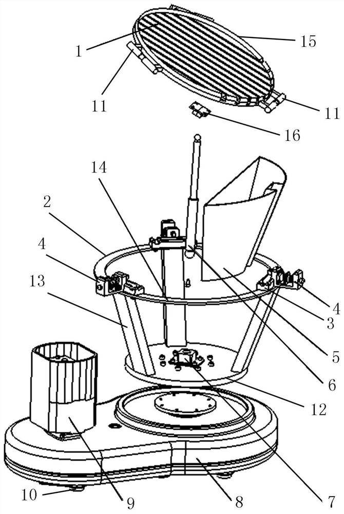
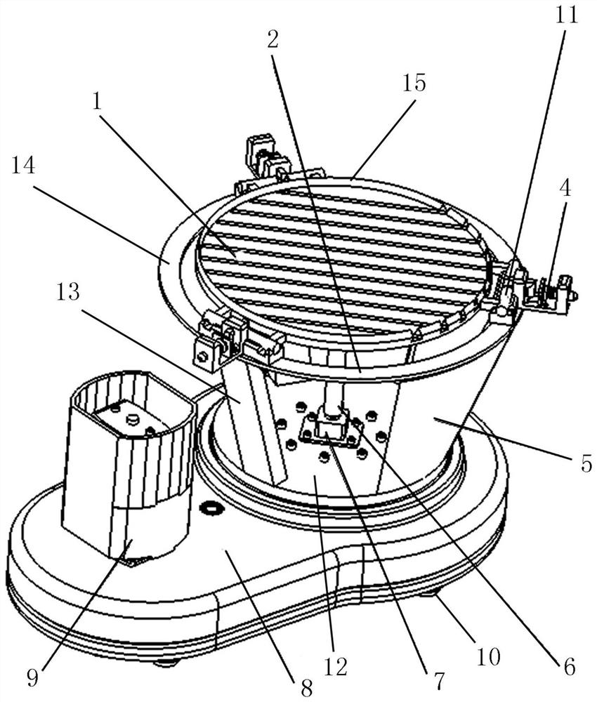
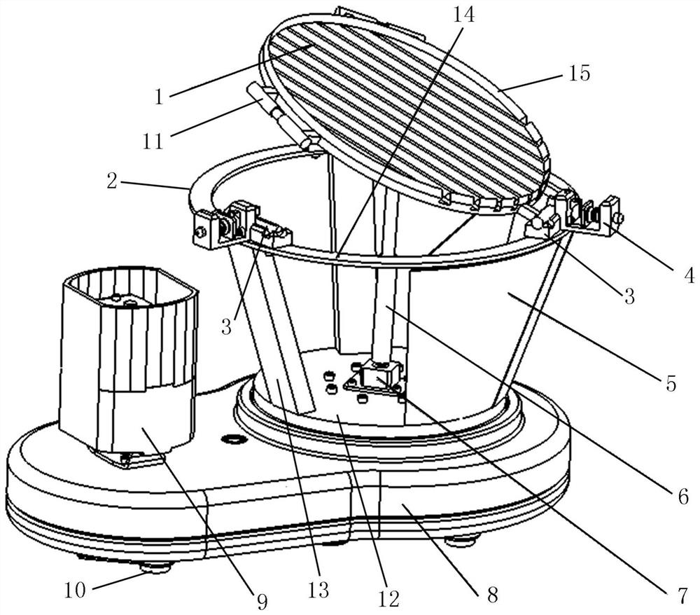
[0022] The present invention is a laser cladding workpiece clamping device with powder recovery function, such as Figure 1-3 As shown, it includes a two-stage horizontal reducer 8, the input shaft of the two-stage horizontal reducer 8 is connected with a motor 9, and the output shaft disk of the two-stage horizontal reducer 8 is fixedly connected with a support frame 2 through a plurality of screws, and the support Cylinder 6 and recovery barrel 5 are respectively fixed in the frame 2, and the telescopic end of cylinder 6 is connected with workbench 1, and the axial direction of cylinder 6 is set along the vertical direction, and workbench 1 is inclined when cylinder 6 piston rod stretches out, and the inclined workbench 1 The lowest end is located directly above the mouth of the recycle bin 5, and the edge of the workbench 1 is flexibly con...


PUM


Abstract

The invention discloses a laser cladding workpiece clamping device having a powder recovering function. The laser cladding workpiece clamping device comprises a two-stage horizontal speed reducer; aninput shaft of the two-stage horizontal speed reducer is connected with a motor; an output shaft disc of the two-stage horizontal speed reducer is connected with a supporting frame; an air cylinder and a recovering barrel are fixed in the supporting frame; the telescopic end of the air cylinder is connected with a workbench; the axial direction of the air cylinder is arranged in the vertical direction; the workbench inclines when a piston rod of the air cylinder stretches out, the lowest end of the inclined workbench is located above a barrel opening of the recovering barrel, the edge of the workbench is movably connected with the supporting frame through a connecting piece, and the connecting piece is of a rotary pair structure. According to the laser cladding workpiece clamping device, rotary parts of different structures can be rapidly and effectively repaired, fixed and installed, and the laser cladding working efficiency is improved; most importantly, powder can be prevented fromsplashing out of the working platform in the cladding process, all unmelted powder can be recycled, the problems of powder pollution and waste in the laser cladding process are effectively solved, andpollution and potential safety hazards in a working place are reduced.

Description

technical field [0001] The invention belongs to the technical field of laser cladding, and relates to a laser cladding workpiece clamping device with the function of recovering powder. Background technique [0002] Laser cladding is an advanced surface modification technology, which is currently widely used in green manufacturing fields such as surface treatment and repair of parts in aviation, automobile, biomedical, construction machinery and other industries. The process adds cladding material to the surface of the part, and uses a high-energy-density laser beam to fuse it together with a thin layer on the surface of the substrate to form a metallurgically bonded material cladding layer. [0003] The existing laser cladding equipment mainly adopts the synchronous powder feeding method to carry the cladding powder to the laser melting working area by airflow. The synchronous powder feeding method has the characteristics of easy automation, high laser energy absorption rat...

Claims


Application Information

Patent Timeline
Patent Type & Authority Applications(China)
IPC IPC(8): C23C24/10
CPCC23C24/10Y02P10/25
Inventor 张建广韩斌慧赵轶飞林坤张爱琴张超
Owner XIAN AERONAUTICAL POLYTECHNIC INST
Why Eureka
Try Eureka