Actuating a metal-oxide semiconductor field-effect transistor

A semiconductor and drive control technology, applied in transistors, semiconductor devices, control/regulation systems, etc., and can solve problems such as high loss

Pending Publication Date: 2021-01-08
SIEMENS AG
View PDF0 Cites 1 Cited by
  • Summary
  • Abstract
  • Description
  • Claims
  • Application Information

AI Technical Summary

Problems solved by technology

The problem therefore arises especially in these converters that, when all MOSFETs are switched off by mistake, reverse currents through the MOSFETs cause high losses

Method used


Image

  • Actuating a metal-oxide semiconductor field-effect transistor
  • Actuating a metal-oxide semiconductor field-effect transistor
  • Actuating a metal-oxide semiconductor field-effect transistor

Examples


Embodiment Construction

[0026] Parts corresponding to one another in the figures are provided with the same reference numerals.

[0027] figure 1 MOSFET 1 is shown with a drain terminal D, a source terminal S, a gate terminal G and a body diode 2 . MOSFET 1 is designed as a generally blocking n-channel MOSFET based, for example, on a semiconductor with a wide band gap, for example based on silicon carbide or gallium nitride. The reverse current, ie the current directed (according to the technical current direction) from the source connection S to the drain connection D, flows through the body diode 2 in the off state of the MOSFET 1 .

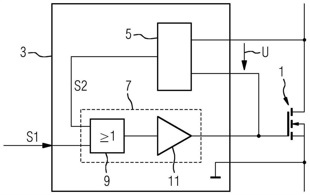
[0028] figure 2 shown as in figure 1 The circuit diagram of MOSFET1 designed in and the first embodiment of the driving and controlling device 3 for driving and controlling MOSFET1 according to the present invention.

[0029]The control device 3 includes a monitoring unit 5 and a control unit 7 . The monitoring unit 5 is designed to determine whether the body di...


PUM


Abstract

The invention relates to a method and an actuation assembly (3) for actuating a MOSFET (1), in particular a MOSFET (1) based on a semiconductor with a wide band gap. According to the invention, a monitoring process is carried out to determine whether the body diode (2) of the MOSFET (1) is electrically conductive. If the body diode (2) is electrically conductive, the MOSFET (1) is activated, and if the body diode (2) is electrically blocking, the MOSFET is actuated on the basis of an actuation signal (S1).

Description

technical field [0001] The invention relates to a method and control for controlling a metal oxide semiconductor field effect transistor (MOSFET=metal oxide semiconductor field effect transistor), in particular a MOSFET based on a semiconductor with a wide bandgap (wide bandgap semiconductor) device. Background technique [0002] The MOSFET is reverse conducting and has a pn junction between the base and drain, when the base and drain are electrically connected, the pn junction acts as an intrinsic diode, this intrinsic diode is called the reverse diode or body diode. If the MOSFET is turned off, reverse current flows through the body diode. Due to the high resistance of the body diode, high losses occur here. When in the event of a fault all the MOSFETs of the converter are disconnected and a reverse current flows through the body diodes of the MOSFETs of the converter from the supply network connected to the converter or from a load connected to the converter Significa...

Claims


Application Information

Patent Timeline
Patent Type & Authority Applications(China)
IPC IPC(8): H02M1/08H02M3/158H03K17/082H03K17/16H02M1/00
CPCH02M1/083H02M3/1588H03K17/0822H03K17/165H02M1/0058Y02B70/10H02M1/08
Inventor 马克-马蒂亚斯·巴克兰于尔根·伯默尔马丁·黑尔斯佩尔埃伯哈德·乌尔里希·克拉夫特贝恩德·拉斯卡安德烈亚斯·纳格尔斯特凡·汉斯·维尔纳·舍内沃夫简·魏格尔
Owner SIEMENS AG
Why Eureka
Try Eureka