Automatic edge cutting equipment for microcrystalline plate

A technology for cutting edges and plates, which is applied in the field of automatic edge trimming equipment for microcrystalline plates, and can solve problems such as jumping of microcrystalline plates, formation of sawtooth, and shattering of microcrystalline plates

Inactive Publication Date: 2021-01-12
石小凡
View PDF0 Cites 4 Cited by
  • Summary
  • Abstract
  • Description
  • Claims
  • Application Information

AI Technical Summary

Problems solved by technology

Moreover, compared with natural stone, glass-ceramic decorative panels also have the advantages of uniform strength, simple process, and low cost; The structural form often used by the plate trimming machine is: use the cutter to cut off the outer edge of the microcrystalline plate as a whole, and the huge friction force generated during cutting will easily cause the beating of the microcrystalline plate. Although there are fixtures, it will inevitably cause vibration of various parts. Unevenness will cause inclination, which will have an adverse effect on the trimming, resulting in uneven cutting on the outside, and sometimes jagged edges will be formed on the edge of the microcrystalline sheet, and what is worse is that the entire microcrystalline sheet will be shattered; A large number of microcrystalline plate residues will be produced in the process, if not processed in time, it will pollute the environment and cause damage to related peripheral devices; the existing microcrystalline plate edge trimmer cuts off the outer edge of the microcrystalline plate as a whole , the running speed is slow, which is not conducive to rapid mass production. Therefore, we propose an automatic edge trimming equipment for microcrystalline plates in order to solve the above-mentioned problems

Method used


Image

  • Automatic edge cutting equipment for microcrystalline plate
  • Automatic edge cutting equipment for microcrystalline plate
  • Automatic edge cutting equipment for microcrystalline plate

Examples


Embodiment Construction

[0026] The following description serves to disclose the present invention to enable those skilled in the art to carry out the present invention. The preferred embodiments described below are only examples, and those skilled in the art can devise other obvious variations.

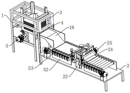
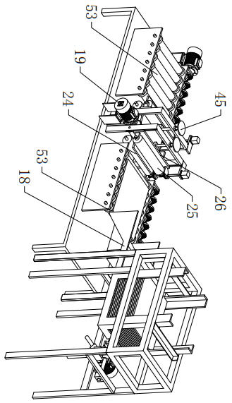
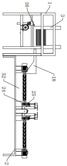
[0027] refer to Figure 1 to Figure 8 As shown, an automatic edge trimming device for microcrystalline plates includes a feeding support 1, a cutting table 2, a feeding drive mechanism, a material shifting mechanism, and an edge trimming mechanism. The feeding support 1 and the cutting table 2 are arranged in parallel, A rectangular feeding basket 3 is arranged on the feeding bracket 1, and the feeding driving mechanism is arranged on the feeding bracket 1. The rectangular feeding basket 3 is provided with a material transfer port 4 near the lower end of the cutting table 2 for conveying the rectangular feeding basket. The microcrystalline plate in 3 moves onto the cutting table 2, and the material moving m...


PUM


Abstract

The invention relates to the technical field of microcrystalline plate processing, in particular to an automatic edge cutting equipment for a microcrystalline plate. The equipment comprises a feedingsupport, a cutting table, a feed driving mechanism, a feed moving mechanism and an edge cutting mechanism, wherein the feeding support and the cutting table are distributed in parallel, a rectangularfeeding basket is arranged on the feeding support, the feed driving mechanism is arranged on the feeding support, the feed moving opening is formed in the lower end, close to the cutting table, of therectangular feeding basket and used for conveying a microcrystalline plate in the rectangular feeding basket to the cutting table, the feed moving mechanism at least comprises two feed moving assemblies, the two feed moving assemblies are arranged on the cutting table in parallel in a spaced mode, the edge cutting mechanism comprises a feed cutting assembly and at least two feed guiding assemblies, the feed cutting assembly is located between the two feed moving assemblies, and the two feed guiding assemblies are arranged on the two sides of the feed cutting assembly. According to the automatic edge cutting equipment, automatic feeding can be achieved, edge cutting efficiency is high, vibration is small, damage to the microcrystal plate is avoided, the microcrystal plate is smooth and tidy after an outer edge is cut off, and production efficiency and production precision are improved.

Description

technical field [0001] The invention relates to the technical field of microcrystalline plate processing, in particular to an automatic edge trimming device for microcrystalline plate. Background technique [0002] Microcrystalline plate is a mixture of microcrystalline and glass made of appropriate glass particles through sintering and crystallization. Its texture is hard, dense and uniform, and there is no pollution in the production process, and the product itself has no radioactive pollution. It is a new type of environmentally friendly green material; the microcrystalline plate looks very different from our common glass, and it has the dual functions of glass and ceramics. characteristics, and the texture on the surface is more inclined to ceramics. Glass-ceramic is brighter than ceramics and tougher than glass. Marble, granite and other natural stones have a rough surface and are prone to dirt, but glass-ceramic does not have this problem. The main component of marb...

Claims


Application Information

Patent Timeline
Patent Type & Authority Applications(China)
IPC IPC(8): C03B33/023
CPCC03B33/023Y02P40/57
Inventor 石小凡
Owner 石小凡
Why Eureka
Try Eureka