High-energy-density deformable batteries
An energy storage unit, energy storage device technology, applied in the direction of batteries, lithium batteries, battery electrodes, etc., can solve problems such as unsatisfactory energy density
- Summary
- Abstract
- Description
- Claims
- Application Information
AI Technical Summary
Problems solved by technology
Method used
Image

Examples
Embodiment Construction
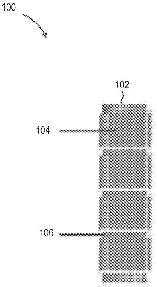
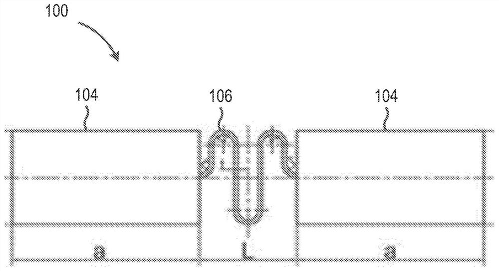
[0026] now refer to Figure 1A , some aspects of the disclosed subject matter include an energy storage device 100 having an axial structure 102 . In some embodiments, energy storage device 100 includes two or more rigid energy storage cells 104 arranged along axial structure 102 . In some embodiments, energy storage device 100 includes a plurality of energy storage units 104 . In some embodiments, a conductive flexible member 106 separates adjacent rigid energy storage units 104 . now refer to Figure 1B , in some embodiments, the energy storage device 100 is configured such that L / a is between 0.30 and 1.0, where L is the length of the conductive flexible member 106, and a is the rigid energy storage unit 104 adjacent to the conductive flexible member energy storage length.
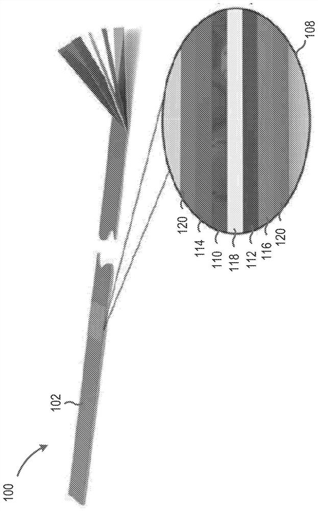
[0027] now refer to Figure 1C , in some embodiments, the axial structure 102 includes a plurality of layers 108 . In some embodiments, the plurality of layers includes an anode layer 110, a cathod...
PUM
 Abstract
Description
Claims
Application Information
 - R&D
- Intellectual Property
- Life Sciences
- Materials
- Tech Scout
- Unparalleled Data Quality
- Higher Quality Content
- 60% Fewer Hallucinations
Browse by: Latest US Patents, China's latest patents, Technical Efficacy Thesaurus, Application Domain, Technology Topic, Popular Technical Reports.
© 2025 PatSnap. All rights reserved.Legal|Privacy policy|Modern Slavery Act Transparency Statement|Sitemap|About US| Contact US: help@patsnap.com