Oil gas recovery method
A recovery method, oil and gas technology, applied in separation methods, chemical instruments and methods, dispersed particle separation, etc., to achieve the effect of broad application prospects, good absorption effect, and good effect
- Summary
- Abstract
- Description
- Claims
- Application Information
AI Technical Summary
Problems solved by technology
Method used
Image

Examples
Embodiment 1
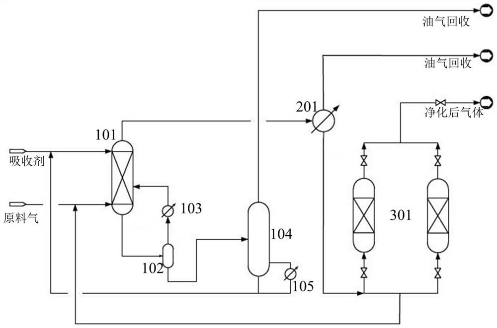
[0135] This embodiment provides a method for recovering oil and gas, and the device for recovering oil and gas used in the method is as follows: figure 1 As shown, the device includes an absorption unit, a condensation unit and an adsorption-desorption unit.
[0136] The absorption unit includes an absorption tower 101; the upper side of the absorption tower 101 is provided with a first absorbent inlet; the lower side of the absorption tower 101 is provided with a feed gas inlet; the absorption tower 101 is provided with a bottom absorbent outlet and the gas outlet after absorption at the top; the middle part of the absorption tower 101 is also provided with a second absorbent inlet; the bottom absorbent outlet is connected with the second absorbent inlet; between the bottom outlet and the second absorbent inlet is provided with A flow splitter 102; a first heat exchange device 103 is provided between the flow splitter 102 and the second absorbent inlet; the top absorption gas...
Embodiment 2
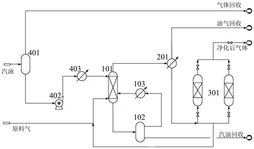
[0146] This embodiment provides a method for recovering oil and gas, and the device for recovering oil and gas used in the method is as follows: figure 2 As shown, the device includes an absorption unit, a condensation unit and an adsorption-desorption unit.
[0147] The absorption unit includes an absorption tower 101; the upper side of the absorption tower 101 is provided with a first absorbent inlet; the lower side of the absorption tower 101 is provided with a feed gas inlet; the absorption tower 101 is provided with a bottom absorbent outlet and the gas outlet after absorption at the top; the middle part of the absorption tower 101 is also provided with a second absorbent inlet; the bottom absorbent outlet is connected with the second absorbent inlet; between the bottom outlet and the second absorbent inlet is provided with A flow splitter 102; a first heat exchange device 103 is provided between the flow splitter 102 and the second absorbent inlet; the top absorption ga...
Embodiment 3
[0158] This embodiment provides a method for recovering oil and gas, and the device for recovering oil and gas used in the method includes an absorption unit, a condensation unit and an absorption and desorption unit.
[0159] The absorption unit includes an absorption tower; the upper side of the absorption tower is provided with a first absorbent inlet; the lower side of the absorption tower is provided with a feed gas inlet; the absorption tower is provided with a bottom absorbent outlet and a top absorbent gas outlet; the middle part of the absorption tower is also provided with a second absorbent inlet; the bottom absorbent outlet is connected to the second absorbent inlet; a splitter is arranged between the bottom outlet and the second absorbent inlet; the A first heat exchange device is arranged between the splitter and the second absorbent inlet; the top absorption gas outlet is connected with a condensing unit.
[0160] The absorption unit also includes a desorption t...
PUM
 Abstract
Description
Claims
Application Information
 - R&D
- Intellectual Property
- Life Sciences
- Materials
- Tech Scout
- Unparalleled Data Quality
- Higher Quality Content
- 60% Fewer Hallucinations
Browse by: Latest US Patents, China's latest patents, Technical Efficacy Thesaurus, Application Domain, Technology Topic, Popular Technical Reports.
© 2025 PatSnap. All rights reserved.Legal|Privacy policy|Modern Slavery Act Transparency Statement|Sitemap|About US| Contact US: help@patsnap.com