Weld structure and manufacturing method thereof

A manufacturing method and butt weld technology, applied in the direction of manufacturing tools, welding equipment, arc welding equipment, etc., can solve problems such as weld crack failure, water leakage, etc., achieve reliable operation and use, solve thermal corrosion, and avoid direct heat radiation Effect

Active Publication Date: 2021-03-16
中国空气动力研究与发展中心超高速空气动力研究所 +1
View PDF12 Cites 0 Cited by
  • Summary
  • Abstract
  • Description
  • Claims
  • Application Information

AI Technical Summary

Problems solved by technology

[0004] Due to the working characteristics of ultra-high temperature and high pressure medium outside the weld and internal water cooling, there is an extremely harsh working environment in the weld area. According to the past use results, the weld in this part often suffers from crack failure and water leakage. occur

Method used


Image

  • Weld structure and manufacturing method thereof
  • Weld structure and manufacturing method thereof
  • Weld structure and manufacturing method thereof

Examples


Embodiment Construction

[0035] The technical solutions of the present invention are further described in detail below with reference to the accompanying drawings, but the protection scope of the present invention is not limited to the following.

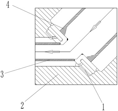
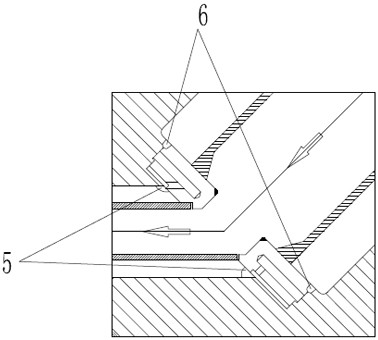
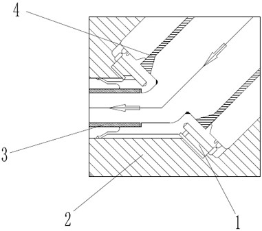
[0036] Refer to the welding structure of the existing valve seat 1 and valve body 2 figure 1 , The entire valve seat 1 cooling system consists of: valve body 2, valve seat 1, tail insulation barrel 3 and head insulation barrel 4.

[0037] The cooling water flows in from the cooling hole at the head of the valve seat 1, and is introduced into the inner center of the valve seat 1 through the guide holes around the valve seat 1, and then transferred to the tail of the valve seat 1, thereby realizing the cooling of the valve seat.

[0038] The tail insulation barrel 3 and the head insulation barrel 4 play the role of slowing down the speed of the ultra-high temperature medium reaching the weld and reducing the temperature. The flow direction of the ultra-high t...


PUM

PropertyMeasurementUnit
mechanical strengthaaaaaaaaaa

Abstract

The invention discloses a welding seam structure and a manufacturing method thereof, which are suitable for the connection of a valve seat and a valve body. The welding seam structure includes a tail butt welding seam and a head butt welding seam. With the setting of the heat preservation barrel at the head, the occurrence of stress fatigue failure of the weld is minimized, and at the same time, the weld avoids the direct heat radiation of the ultra-high temperature medium. The setting of the weld in the heat affected zone of the head makes the entire weld The area is safer and more reliable under harsh working conditions. The setting of weld strain grooves and weld strain zones can effectively prolong the occurrence of weld fatigue failure. With the same mechanical strength, the tail butt weld and head butt weld are used to connect the valve seat and the valve body to form equal strength welds, which improves the overall strength of the weld and eliminates the defect of cracks at the root of the corner weld.

Description

technical field [0001] The present invention relates to the technical field of welding, in particular to a welding seam structure and a manufacturing method thereof. Background technique [0002] At present, in the hypersonic wind tunnel equipment, the high-pressure blow-down-vacuum suction transient wind tunnel is widely used in the test objects for aerodynamic / thermal, aerodynamic layout, Jet flow control and other testing and experimental computing fields. [0003] Due to the special requirements of the system for the rapid release of the ultra-high temperature and high pressure test medium in the heater, a quick-opening valve is provided at the inlet end of the gas supply. The maximum design temperature at the inlet can reach 1000°C, and the design pressure is more than 12MPa), and the outlet side has the characteristics of vacuum. In order to ensure the absolute isolation of the medium on both sides of the valve, high requirements are placed on the thermal deformation ...

Claims


Application Information

Patent Timeline
Patent Type & Authority Patents(China)
IPC IPC(8): B23K33/00B23K9/167B23K9/02B23K9/235B23P15/00
CPCB23K9/02B23K9/167B23K9/235B23K33/004B23P15/00
Inventor 侯峰伟赵健吴斌彬许晓斌王南天母波张大辉于成亮杨忠义杨凯旋
Owner 中国空气动力研究与发展中心超高速空气动力研究所
Why Eureka
Try Eureka