A silicon carbide crystal removal device

A silicon carbide and crystal technology is applied in the field of silicon carbide crystal removal devices, which can solve the problems of cracking and uneven crystal shedding, and achieve the effect of reducing friction.

Active Publication Date: 2021-03-09
宁波合盛新材料有限公司
View PDF5 Cites 0 Cited by
  • Summary
  • Abstract
  • Description
  • Claims
  • Application Information

AI Technical Summary

Problems solved by technology

[0004] Aiming at the deficiencies of the prior art, the present invention provides a silicon carbide crystal removal device, which solves the problem that the existing silicon carbide crystal removal device uses a direct ejection method to make the crystal fall off unevenly and cause cracking

Method used


Image

  • A silicon carbide crystal removal device
  • A silicon carbide crystal removal device
  • A silicon carbide crystal removal device

Examples


Embodiment 1

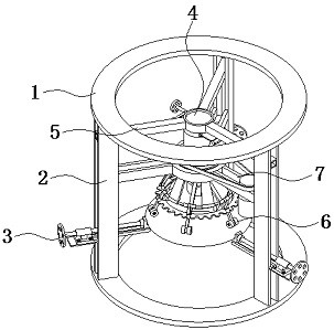
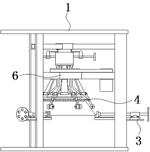
[0026] Embodiment one, such as Figure 1-8 As shown, a device for removing a silicon carbide crystal includes two supporting plates 1 and three connecting rods 2, the three connecting rods 2 are located between the two supporting plates 1, and the upper and lower ends of the three connecting rods 2 are respectively connected to The sides of the two support plates 1 close to each other are fixedly connected, and a buffer pad can be placed inside the support plate 1 below.

[0027] The lower ends of the three connecting rods 2 are all equipped with a clamping mechanism 3, and an extruding mechanism 4 is arranged between the upper ends of the three connecting rods 2. The extruding mechanism 4 is fixedly connected with the three connecting rods 2 through three horizontal plates A5, and the three connecting rods 2 are fixedly connected. A striking mechanism 6 is arranged between the connecting rods 2, and the striking mechanism 6 is fixedly connected with the three connecting rods ...

Embodiment 2

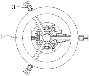
[0030] Embodiment two, such as Figure 1-7 As shown, the clamping mechanism 3 includes a guide rail 301, a clamping block 302, a threaded rod B303 and a threaded sleeve B304, the guide rail 301 is fixedly connected with the connecting rod 2, the lower end of the clamping block 302 is slidingly connected with the guide rail 301, and the threaded sleeve B304 is connected with the guide rail 301. The outer end is fixedly connected, one end of the threaded rod B303 is rotatably connected with the clamp block 302, and the other end of the threaded rod B303 passes through the threaded sleeve B304 and is threadedly connected with it.

[0031]When in use, the crucible or the seed crystal bracket can be fixed by adjusting the clamping mechanism 3, and the pulley 603 is driven to rotate by controlling the rotation of the motor 602, and then the fixed ring 604 starts to rotate under force, driving the rocker 607 to rotate, and the rocker When 607 rotates along the special-shaped wheel 41...


PUM


Abstract

The invention provides a silicon carbide crystal removing device, which relates to the field of silicon carbide production. The device includes two supporting plates and three connecting rods, the three connecting rods are located between the two supporting plates, the upper and lower ends of the three connecting rods are respectively fixedly connected with the sides of the two supporting plates which are close to each other, and the three connecting rods The lower ends of each are equipped with a clamping mechanism, and an extruding mechanism is arranged between the upper ends of the three connecting rods, and the extruding mechanism is fixedly connected with the three connecting rods through three horizontal plates A. The silicon carbide crystal removal device is equipped with a clamping mechanism, a squeezing mechanism and a knocking mechanism. By adjusting the clamping mechanism, the crucible or the seed crystal bracket can be fixed. By controlling the rotation of the motor, the pulley is driven to rotate. The two wedges The plates can be overlapped, the wedge-shaped plate gradually squeezes the force-bearing plate, and the pressure plate exerts slow and uniform pressure on the crystal, which can make the crystal fall off completely, which solves the problem of uneven crystal fall-off and rupture caused by the direct ejection method in the prior art.

Description

technical field [0001] The invention relates to the field of silicon carbide production, in particular to a silicon carbide crystal removing device. Background technique [0002] Silicon carbide (SiC) single crystal has excellent semiconductor physical properties such as high thermal conductivity, high breakdown voltage, extremely high carrier mobility, and high chemical stability, and can be made into high-frequency semiconductors that work under high temperature and strong radiation conditions. , High-power electronic devices and optoelectronic devices have great application value in the fields of national defense, high technology, industrial production, power supply, and transformation, and are regarded as the third-generation wide-bandgap semiconductor materials with great development prospects. [0003] At present, physical vapor deposition (PVT) is a commonly used method for growing silicon carbide crystals. In this method, silicon carbide powder is used as the raw mat...

Claims


Application Information

Patent Timeline
Patent Type & Authority Patents(China)
IPC IPC(8): C30B23/00C30B29/36
CPCC30B23/00C30B29/36
Inventor 邹小燕李兴霞姚文申兴
Owner 宁波合盛新材料有限公司
Why Eureka
Try Eureka