MTPV compensation method and system for drive permanent magnet synchronous motor

A technology of permanent magnet synchronous motor and compensation method, which is applied in the direction of control system, control generator, vector control system, etc., can solve the problems of increased loss and low voltage utilization rate, so as to reduce loss and improve low voltage utilization rate Effect

Active Publication Date: 2021-01-15
WUHAN KOTEI INFORMATICS
View PDF7 Cites 0 Cited by
  • Summary
  • Abstract
  • Description
  • Claims
  • Application Information

AI Technical Summary

Problems solved by technology

However, in the real-time control algorithm, due to the influence of temperature, resistance, inductance, harmonics, eddy current loss and other factors
At a certain speed, the stator current may cause low voltage utilization and large losses

Method used


Image

  • MTPV compensation method and system for drive permanent magnet synchronous motor
  • MTPV compensation method and system for drive permanent magnet synchronous motor
  • MTPV compensation method and system for drive permanent magnet synchronous motor

Examples


Embodiment 1

[0046] Embodiment 1 provided by the present invention is an embodiment of the MTPV compensation method for driving a permanent magnet synchronous motor provided by the present invention, and the embodiment of the method includes:

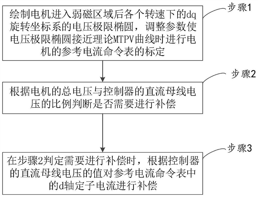
[0047] Step 1. Draw the voltage limit ellipse of the dq rotating coordinate system at each speed after the motor enters the field weakening area, and adjust the parameters to make the voltage limit ellipse close to the theoretical MTPV curve, and then calibrate the reference current command table of the motor.

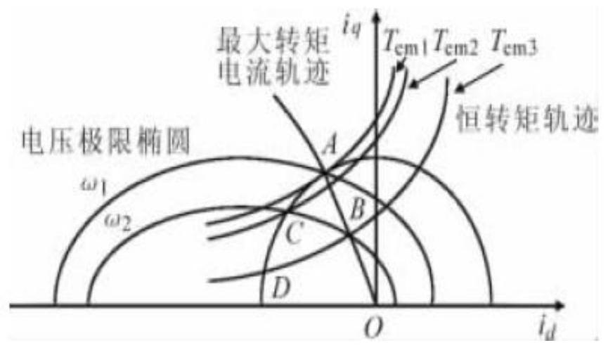
[0048] The process of drawing a voltage limit ellipse involves:

[0049]After the voltage reaches the limit of the output voltage of the inverter, the speed of the motor is continuously increased by increasing the d-axis stator current. At this time, the voltage limit ellipse at each speed is drawn.

[0050] The output voltage of the inverter is limited by the DC input voltage. When the magnetic synchronous motor is controlled, when the volt...

Embodiment 2

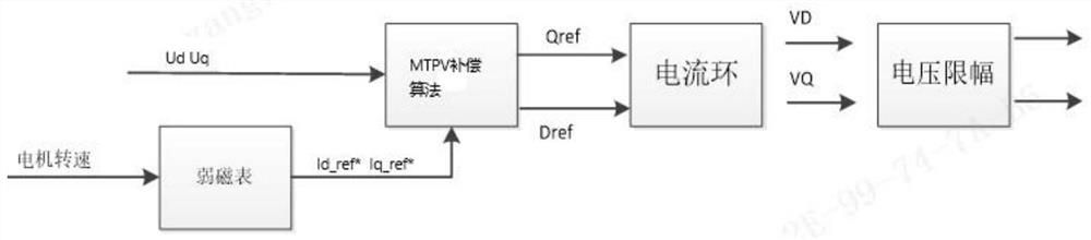
[0075] Embodiment 2 provided by the present invention is an embodiment of a MTPV compensation system for driving a permanent magnet synchronous motor provided by the present invention, such as Figure 5 Shown is the structural block diagram of the embodiment of a kind of drive permanent magnet synchronous motor MTPV compensation system provided by the present invention, by Figure 5 It can be seen that the system includes: the system includes: a reference current command table calibration module 101 , a compensation judgment module 102 and a compensation calculation module 103 .

[0076] The reference current command table calibration module 101 is used to draw the voltage limit ellipse of the dq rotating coordinate system at various speeds after the motor enters the field weakening area, and adjust the parameters to make the voltage limit ellipse close to the theoretical MTPV curve to calibrate the reference current command table of the motor .

[0077] The compensation judg...


PUM


Abstract

The invention relates to an MTPV compensation method and system for a drive permanent magnet synchronous motor. The method comprises steps of drawing a voltage limit ellipse of a dq rotating coordinate system at each rotating speed after the motor enters a weak magnetic region, adjusting parameters, and carrying out the calibration of a reference current command table of the motor when the voltagelimit ellipse is close to a theoretical MTPV curve; judging whether compensation is needed or not according to the proportion of the total voltage of the motor to the direct-current bus voltage of the controller; and compensating the d-axis stator current in the reference current command table according to the value of the DC bus voltage of the controller when it is judged that compensation needsto be performed. The dq-axis voltage, namely the total voltage us of the motor, is used as a condition for correcting the stator current id value in the reference current command table, and the d-axis stator current in the reference current command table is compensated according to the value of the direct-current bus voltage of the controller, so a purpose of compensation is achieved, the voltageutilization rate of the inverter is improved, and loss is reduced.

Description

technical field [0001] The invention relates to the field of motor control, in particular to an MTPV compensation method and system for driving a permanent magnet synchronous motor. Background technique [0002] The permanent magnet synchronous motor for vehicles is the core component of driving the car. High-performance motor control determines the rapid development of electric vehicles. The permanent magnet synchronous motor speed control system generally consists of DC power supply, inverter, controller and motor. Currently, the drive There are two main motor drives for electric vehicles: vector control and direct torque control. [0003] Vector control is actually the control of the three-phase stator current. By converting the three-phase stator alternating current into two-phase direct current, the magnitude of the dq axis current is directly controlled to realize the vector control of the permanent magnet synchronous motor. The torque of the motor is controlled by co...

Claims


Application Information

Patent Timeline
Patent Type & Authority Applications(China)
IPC IPC(8): H02P21/14H02P21/22H02P21/00
CPCH02P21/0089H02P21/14H02P21/22
Inventor 程德心吴应军杨峰
Owner WUHAN KOTEI INFORMATICS
Why Eureka
Try Eureka