
Patsnap Eureka
For R&D, Patsnap Eureka makes reading and utilizing patents & technical documents easy.
Patsnap Eureka AIR
Designed for self-driven R&D workflows. Generate viable solutions, solve complex R&D challenges, empower your innovation with AI.

Patsnap Eureka Materials
Designed for material experts only. Revolutionize your material R&D, from search, analyze, to developing new materials.

TechResearch
Generate reliable direction feasibility study reports for your R&D in just a few steps.

TechSeek
Discover and master advanced knowledge NOW. Basics, ideas, possibilities, all at once.

TechMind
As an expert in R&D Theories, TechMind can generates customized viable solutions instantly.

TechRisk
Analyze your overall solution with one click, know your potential R&D risks in advance.

TechMonitor
Get weekly tech updates, stay abreast of the latest tech innovations and key insights.
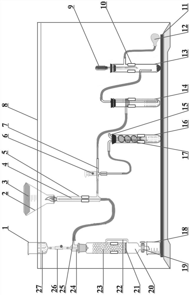
Integrated experimental device and method for combustion of hydrogen in chlorine
An experimental device, hydrogen technology, applied in the direction of educational appliances, instruments, teaching models, etc., can solve the problems of non-compliance with green chemistry and environmental protection, increase the intensity of experimental preparation work, and consume large amounts of reactants, etc., so as to facilitate classroom demonstrations , avoid the escape of harmful gas, and facilitate the effect of manual operation
- Summary
- Abstract
- Description
- Claims
- Application Information
AI Technical Summary
Problems solved by technology
Method used
Image

Examples
Embodiment Construction
[0017] In order to make the object, technical solution and advantages of the present invention clearer, the present invention will be further described in detail below in conjunction with the accompanying drawings and embodiments. It should be understood that the specific embodiments described here are only used to explain the present invention, not to limit the present invention.
[0018] Such as figure 1 As shown, the integrated experimental device for the combustion of hydrogen in chlorine in this embodiment consists of a liquid storage cup 1, a conical flask 2, a sponge pad 3, an inner tube 4, a combustion nozzle 5, a three-way valve 6, a three-way conduit 7, Bracket 8, rubber dropper 9, clip 10, base 11, one-way balloon 12, third test tube 13, second test tube 14, air outlet tube 15, first test tube 16, sponge strip 17, beaker 18, drain valve 19. Reactor 20, sieve plate 21, air pressure balance pipe 22, solid reaction reagent 23, connector 24, air guide tube 25, flow reg...
PUM
 Abstract
Description
Claims
Application Information
 - R&D Engineer
- R&D Manager
- IP Professional
- Industry Leading Data Capabilities
- Powerful AI technology
- Patent DNA Extraction
Browse by: Latest US Patents, China's latest patents, Technical Efficacy Thesaurus, Application Domain, Technology Topic, Popular Technical Reports.
© 2024 PatSnap. All rights reserved.Legal|Privacy policy|Modern Slavery Act Transparency Statement|Sitemap|About US| Contact US: help@patsnap.com