
Catalyst slurry for membrane electrode, method for producing same, catalyst-coated membrane, and membrane electrode

A catalyst slurry and membrane electrode technology, which is applied in the field of catalyst coating membrane and membrane electrode, can solve the problems of affecting the performance of CCM and prone to cracks in the catalyst layer.

Inactive Publication Date: 2021-01-22
SINOHYKEY TECH CO LTD
View PDF6 Cites 6 Cited by
  • Summary
  • Abstract
  • Description
  • Claims
  • Application Information

AI Technical Summary

Problems solved by technology

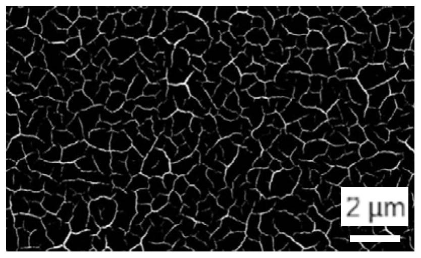
However, the research and development personnel found that the CCM is prepared by the method of cathode-anode direct coating, and cracks are prone to appear on the catalyst layer, which affects the performance of CCM.

Method used


Image

  • Catalyst slurry for membrane electrode, method for producing same, catalyst-coated membrane, and membrane electrode
  • Catalyst slurry for membrane electrode, method for producing same, catalyst-coated membrane, and membrane electrode
  • Catalyst slurry for membrane electrode, method for producing same, catalyst-coated membrane, and membrane electrode

Examples


Embodiment 1

[0025] The method for preparing catalyst coating film, comprises the following steps:

[0026] (1) Catalyst slurry preparation:

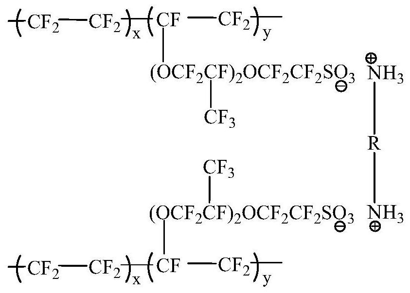
[0027] First weigh 5-12% of platinum and carbon particle catalyst, 4-8% of perfluorosulfonic acid resin and 80-91% of solvent, among which perfluorosulfonic acid resin uses Chemours D2020, platinum and carbon particle catalyst Tec10F50e produced by Tanaka Precious Metals (TKK) in Japan is selected. The solvent is 50-99 parts of water and 1-50 parts of low-boiling alcohol solvent. The low-boiling alcohol solvent is methanol, ethanol, n-propanol, isopropanol, n-butanol or isobutanol; and then weigh butylenediamine accounting for 1% mass fraction of perfluorosulfonic acid resin as an additive for later use.

[0028] The concrete preparation process of catalyst slurry is as follows:

[0029] First, disperse the perfluorosulfonic acid resin in the solvent to form a perfluorosulfonic acid resin dispersion; then slowly add the additive butanediamine into...

Embodiment 2

[0037] The amount of the additive in step (1) of Example 1 was changed to 3% by mass of the perfluorosulfonic acid resin. The remaining steps are the same as in Embodiment 1.

[0038] The mass of the additives can be selected within the range of 0.1% to 10% of the mass of the perfluorosulfonic acid resin, and will not be listed here.

[0039] The preferred range of the mass of the additive is 0.5% to 5% of the mass of the perfluorosulfonic acid resin. This is because: if the amount of additive is small, the effect will not be obvious; if the amount is too large, on the one hand, it will affect other properties of the catalyst slurry, and on the other hand, it will be difficult to remove it in the membrane electrode.

[0040]The additive can also be selected from other compounds or polymers containing at least two nitrogen-containing functional groups, such as organic aliphatic primary amines, organic aliphatic secondary amines, organic aliphatic tertiary amines, aromatic amin...


PUM

PropertyMeasurementUnit
Viscosityaaaaaaaaaa

Abstract

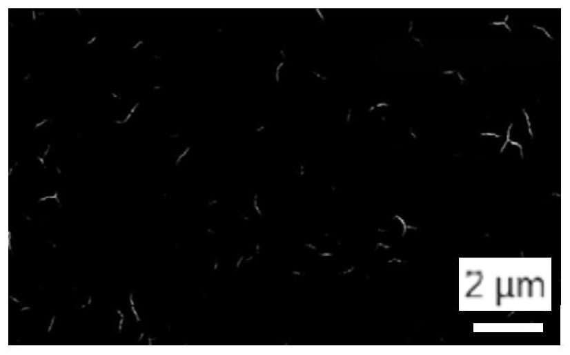
The invention belongs to the field of fuel cells, and particularly relates to catalyst slurry for a membrane electrode, a preparation method of the catalyst slurry, a catalyst coating membrane and themembrane electrode. The catalyst slurry for the membrane electrode is prepared from the following components: a catalyst, perfluorosulfonic acid resin, a solvent and an additive, wherein the additiveis a compound or a polymer containing at least two nitrogen-containing functional groups. By using the catalyst slurry and adopting a cathode and anode direct coating method to prepare a catalyst coating film, the catalyst coating film with few cracks can be prepared.

Description

technical field [0001] The invention belongs to the field of fuel cells, and in particular relates to a catalyst slurry for a membrane electrode, a preparation method thereof, a catalyst coating membrane, and a membrane electrode. Background technique [0002] Membrane Electrode Assembly (MEA) is the core component of a fuel cell, mainly composed of an anode gas diffusion layer, an anode catalyst layer, a proton exchange membrane, a cathode catalyst layer and a cathode gas diffusion layer, of which the anode catalyst layer, proton exchange membrane The three-in-one structure composed of the cathode catalyst layer and the cathode catalyst layer is a catalyst coated membrane (CCM, Catalyst Coated Membrane). [0003] At present, most of the CCMs are prepared by heat transfer method. The method of hot press transfer is to first coat the slurry (including catalyst, resin and solvent) on the back film, and then transfer from the back film to the proton exchange membrane under hig...

Claims


Application Information

Patent Timeline
IPC IPC(8): H01M4/92H01M4/88H01M4/86H01M8/1004
CPCH01M4/8663H01M4/881H01M4/926H01M8/1004Y02E60/50Y02P70/50
Inventor 杨云松赵明全莫善云叶思宇邹渝泉唐军柯孙宁
Owner SINOHYKEY TECH CO LTD
Learn More