Liquid flow cavitation device

A technology of cavitation and uniform arrangement, which is applied in the fields of oil, natural gas, coalbed methane, and uranium mining. effect, increase the effect of transformation effect

Pending Publication Date: 2021-01-29
刘杰
View PDF1 Cites 3 Cited by
  • Summary
  • Abstract
  • Description
  • Claims
  • Application Information

AI Technical Summary

Problems solved by technology

[0004] However, hydraulic fracturing has the following disadvantages: (1) The process is complicated and the operation cost is high
(2) Serious pollution to oil wells and formations
(3) Great damage to oil wells and formations
In addition, improper drainage can cause increased damage to the reservoir, which can lead to proppant backflow, which can cause permanent damage to the formation and well
(4) The introduction of artificial trunk fractures intensifies the heterogeneity of the reservoir, which may bring adverse effects on the development of oil and gas reservoirs
[0006] However, ultrasonic cavitation has the following disadvantages: (1) Ultrasonic cavitation can only be used for plugging near the wellbore
Therefore, the cavitation effect produced by ultrasonic waves can only act on the near-wellbore area, and the maximum effective radius is only 15 meters, so the effect is limited
(2) The cavitation area is in a non-flowing state, and the cavitation area (or cavitation) formed around the cavitator is limited in scope. With the increase of hydrostatic (external) pressure, it cannot Interruption of fluid flow creates air pockets
According to the requirements of cavitation value, in order to make the liquid flow gap, the liquid must be pumped at a very high speed, but not in all cases, such a high speed can be obtained, especially in deep wells or extended pipelines; at very high Under external hydrostatic pressure, such as in deep wells, the cavitation effect cannot be obtained with ul

Method used


Image

  • Liquid flow cavitation device
  • Liquid flow cavitation device
  • Liquid flow cavitation device

Examples


Embodiment Construction

[0044] Various exemplary embodiments of the present invention will now be described in detail with reference to the accompanying drawings. It should be noted that the relative arrangements of components and steps, numerical expressions and numerical values ​​set forth in these embodiments do not limit the scope of the present invention unless specifically stated otherwise.

[0045] The following description of at least one exemplary embodiment is merely illustrative in nature and in no way taken as limiting the invention, its application or uses.

[0046] Techniques and devices known to those of ordinary skill in the relevant art may not be discussed in detail, but where appropriate, such techniques and devices should be considered part of the description.

[0047] In all examples shown and discussed herein, any specific values ​​should be construed as exemplary only, and not as limitations. Therefore, other instances of the exemplary embodiment may have different values.

...


PUM


Abstract

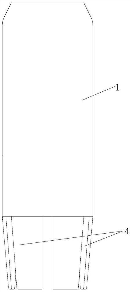
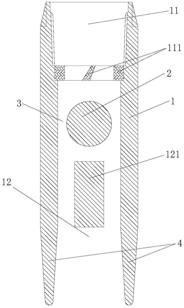
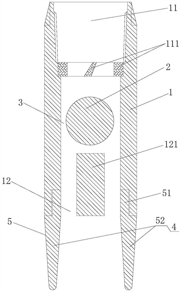
The invention discloses a liquid flow cavitation device. The liquid flow cavitation device comprises a shell and a working medium, wherein the shell is provided with a top opening and a bottom opening, the working medium is limited in an inner cavity of the shell and can move freely, and a flow channel for liquid flow to flow through is formed between the working medium and the cavity wall of theinner cavity of the shell; and the cavitation device further comprises a resonance empennage which is located on the shell and extends out of the end face of the bottom opening of the shell in the axial direction of the cavitation device. According to the liquid flow cavitation device, the cavitation effect of a cavitator can be further enhanced, the transformation effect on an underground rock stratum is improved, and the seepage capacity and the recovery ratio of a reservoir are improved.

Description

technical field [0001] The invention relates to the fields of petroleum, natural gas, coal bed methane and uranium mining, in particular to a liquid flow cavitation device. Background technique [0002] At present, there are two main technologies used in oil exploitation, one is hydraulic fracturing technology, and the other is ultrasonic cavitation technology. [0003] Hydraulic fracturing is an oil augmentation technology that injects fracturing fluid into the oil layer to create a main fracture to change the flow state of the oil flow. The 1980s was a relatively important stage in the development history of hydraulic fracturing, and it gradually became an important technical means in the field of oil and gas, especially low-permeability oil and gas exploration and development. The mechanism of hydraulic fracturing stimulation: When the surface high-pressure pump group injects high-viscosity liquid into the well with a displacement exceeding the absorption capacity of the...

Claims


Application Information

Patent Timeline
IPC IPC(8): E21B43/25E21B43/26E21B28/00
CPCE21B43/25E21B43/26E21B28/00
Inventor 刘杰
Owner 刘杰
Why Eureka
Try Eureka