
Garbage treatment equipment for river pollution treatment

A technology for waste treatment equipment and pollution control, which is applied in grain treatment, lighting and heating equipment, special-purpose ships, etc. It can solve the problems of existing risks and labor-intensive labor, so as to improve efficiency, reduce the risk of falling into the water, increase the Carrying capacity effect

Inactive Publication Date: 2021-02-02
ZIBO CREATION OF MECHANICAL & ELECTRICAL TECH CO LTD
View PDF0 Cites 12 Cited by
  • Summary
  • Abstract
  • Description
  • Claims
  • Application Information

AI Technical Summary

Problems solved by technology

[0005] The purpose of the present invention is to provide a kind of garbage treatment equipment for river pollution control to solve the problem in the prior art that a large amount of manual labor is required and risks exist when salvaging river garbage

Method used


Image

  • Garbage treatment equipment for river pollution treatment
  • Garbage treatment equipment for river pollution treatment
  • Garbage treatment equipment for river pollution treatment

Examples


Embodiment 1

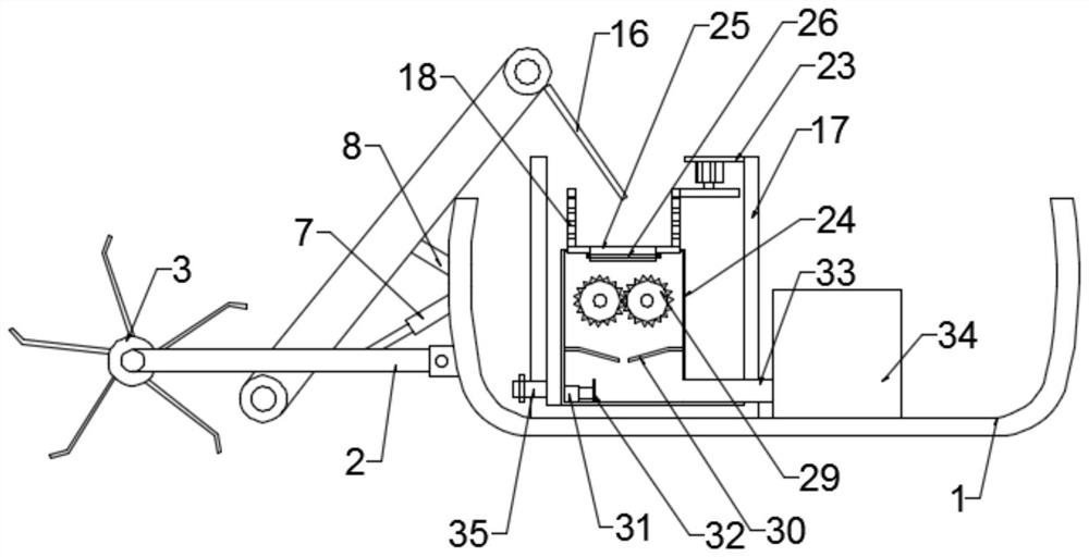
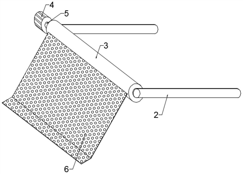
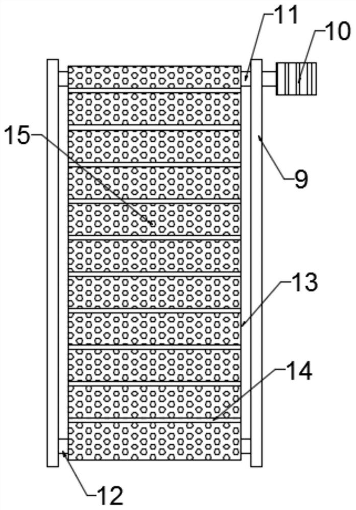
[0033] Such as figure 1 As shown, the embodiment of the present invention provides a kind of garbage treatment equipment for river pollution control, the garbage treatment equipment includes a hull 1, one end of the hull 1 is equipped with a rotating salvage mechanism through two symmetrically arranged connecting rods 2, and the two A leakage transmission mechanism is installed between the two connecting rods 2, and the head end of the leakage transmission mechanism is located below the rotating salvage mechanism; the tail end of the leakage transmission mechanism is provided with a blanking plate 16, and the blanking plate 16 Located on the upper end of the garbage disposal box 17; the inside of the garbage disposal box 17 is equipped with a water-spinning mechanism, and the water-spinning mechanism is installed on the top of the inner cylinder 24 through a rotating assembly, and the side wall of the garbage disposal box 17 is provided with Sewage outlet 35 ; inside the inner...

Embodiment 2

[0047] Such as Figure 5 As shown, in another embodiment provided by the present invention, the rotating assembly includes a chute 27, the chute 27 is set on the side wall of the top opening of the inner cylinder 24, and the bottom of the water spinner 18 is fixed with An annular slider 28 is rotatably installed in the slide groove 27 .

[0048] Installing the water-spinning tube 18 on the top of the inner tube 24 improves the stability of the water-spinning tube 18 when rotating, and the cooperation of the annular slider 28 and the chute 27 ensures that the water-spinning tube 18 can move smoothly in the inner tube 24 turn.


PUM


Abstract

The invention is applicable to the technical field of river treatment, and provides garbage treatment equipment for river pollution treatment. The garbage treatment equipment comprises a ship body, wherein a rotary fishing mechanism is mounted at one end of the ship body through two symmetrically arranged connecting rods, a leaked water conveying mechanism is mounted between the two connecting rods, the head end of the leaked water conveying mechanism is located below the rotary fishing mechanism, a discharging plate is arranged at the tail end of the leaked water conveying mechanism and located at the upper end of a garbage treatment box, a water throwing mechanism is mounted in the garbage treatment box, the water throwing mechanism is mounted at the top of an inner barrel through a rotating assembly, a sewage opening is formed in the side wall of the garbage treatment box, a crushing mechanism and a compression pushing mechanism are sequentially arranged in the inner barrel from topto bottom, and the compression pushing mechanism is connected with a garbage can. According to the garbage treatment equipment, garbage floating on the surface of a river channel can be automaticallycollected and salvaged, the working efficiency is remarkably improved, the safety coefficient is increased, and the risk of falling into water is reduced.

Description

technical field [0001] The invention belongs to the technical field of river channel control, and in particular relates to a garbage treatment device for channel pollution control. Background technique [0002] River course refers to the route through which river water flows, and usually refers to a navigable waterway. River course has a decisive impact on the overall situation of national economic and social development. However, with the rapid development of society and economy, the rapid growth of population and the increasingly frequent economic activities have brought a series of blows to the water environment. [0003] Among them, there are two main reasons for river pollution. One is the massive discharge of pollutants, including domestic sewage, industrial wastewater, pollution of upstream water, and domestic garbage. Destruction of the river ecosystem. In order to treat the river pollution problem and ensure the normal use and management of the river, special envi...

Claims


Application Information

Patent Timeline
Patent Type & Authority Applications(China)
IPC IPC(8): E02B15/10B63B35/32F26B5/08B02C4/02
CPCE02B15/10E02B15/104B63B35/32B02C4/02
Inventor 高忠青
Owner ZIBO CREATION OF MECHANICAL & ELECTRICAL TECH CO LTD
Learn More