Faraday disk, ion mobility tube and ion mobility spectrometer

A technology of ion transfer tube and Faraday disk, applied in the field of ion transfer tube, ion mobility spectrometer, and Faraday disk, can solve problems such as uneven electric field, achieve consistency of deformation, reduce protrusion or depression, stress uniform effect

Pending Publication Date: 2021-02-02
SUZHOU WEIMU INTELLIGENT SYST CO LTD
View PDF0 Cites 0 Cited by
  • Summary
  • Abstract
  • Description
  • Claims
  • Application Information

AI Technical Summary

Problems solved by technology

[0006] Therefore, the technical problem to be solved by the present invention is to overcome the phenomenon that the Faraday disk in the prior art is provided with a circular through hole when used, and the surface of the Faraday disk is heated and expanded to protrude or dent, thereby causing the Faraday disk to be in contact with the front-stage electrode ring. The technical problem of uneven electric field between

Method used


Image

  • Faraday disk, ion mobility tube and ion mobility spectrometer
  • Faraday disk, ion mobility tube and ion mobility spectrometer

Examples


Embodiment 1

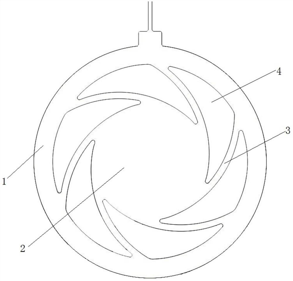
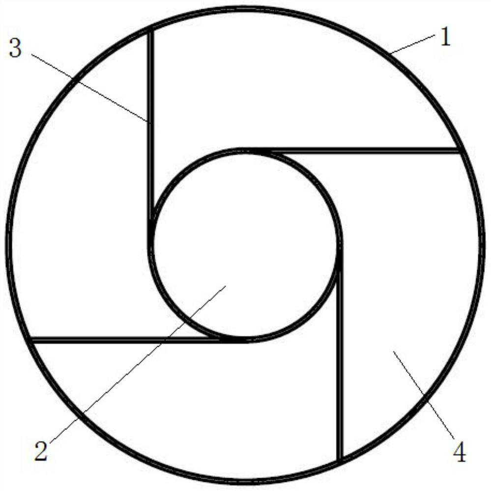
[0042] The Faraday disk of this embodiment, such as Figure 1 to Figure 2 As shown, it includes a mounting ring 1, an ion receiving electrode 2 and a connecting piece 3, wherein the mounting ring 1 and the ion receiving electrode 2 are arranged on the same plane, and the mounting ring 1 is a circular ring, which is made of a material that expands when heated and shrinks when cooled. It is suitable for fixed installation with the inner wall of the transfer tube; the ion receiving electrode 2 has a circular structure, and the ion receiving electrode 2 is arranged in the space in the middle of the installation ring 1, so that there is an annular gap between the installation ring 1 and the ion receiving electrode 2, six The connector 3 is located in the annular gap and its two ends are respectively connected to the installation ring 1 and the ion receiving electrode 2. The six connectors 3 are evenly distributed, so that the Faraday disk has a centrally symmetrical structure, and t...

Embodiment 2

[0051] An ion transfer tube according to this embodiment includes an outer tube, in which an ionization zone, a reaction zone, an ion gate, a migration zone and a detection zone are sequentially arranged along the ion transmission direction, an ion reaction device is arranged in the reaction zone, and an ion reaction device is arranged in the migration zone. There is an ion drift device inside, and an ion detection device is installed in the detection area. The ion detection device includes a grid and a Faraday disk.

[0052] The Faraday disk is the Faraday disk in Embodiment 1 above.

[0053] The ion transfer tube in this embodiment is an existing ion transfer tube structure, and the specific structure is not described or limited.


PUM

PropertyMeasurementUnit
thicknessaaaaaaaaaa

Abstract

The invention relates to a Faraday disk, an ion migration tube and an ion mobility spectrometer. The Faraday disk comprises a mounting ring and an ion receiving electrode which are located in the sameplane, the mounting ring is suitable for being connected with the inner wall of a migration tube, connecting pieces are arranged between the ion receiving electrode and the mounting ring, and an avoidance space allowing the connecting pieces to deform is formed between the adjacent connecting pieces; under the action of high temperature, the mounting ring is heated to expand to apply first bias pressure towards the center of the mounting ring to the connecting pieces, the ion receiving electrode is heated to expand to apply second bias pressure away from the center of the mounting ring to theconnecting pieces, the first bias pressure and the second bias pressure are opposite in action direction and act on the connecting pieces at the same time, the connecting pieces are bent and deformed, stress is more uniform, deformation consistency of the multiple connecting pieces is better facilitated, the ion receiving electrode can rotate in the circumferential direction more easily, then thephenomenon that the surface of the ion receiving electrode protrudes or sinks is reduced, and the influence on an electric field between the ion receiving electrode and a front electrode is smaller.

Description

technical field [0001] The invention relates to the technical field of ion mobility spectrometry, in particular to a Faraday disk, an ion mobility tube and an ion mobility spectrometer. Background technique [0002] Ion mobility spectrometry is a detection technique for trace gas samples. Ion mobility spectrometry (IMS), as a gas-phase ion separation and detection technology, is widely used in rapid detection technologies such as explosives, drugs and chemical warfare agents. [0003] The basic principle of ion mobility spectrometry is that under atmospheric pressure conditions, gas phase ions move in an applied electric field. Due to differences in characteristic parameters such as mass, charge number, and collision cross section, different types of ions have different migration rates in a uniform electric field, so the time required for ions to reach the detector is different to achieve separation and detection. [0004] Faraday disk, also known as ion receiver, ion rece...

Claims


Application Information

Patent Timeline
Patent Type & Authority Applications(China)
IPC IPC(8): H01J49/02H01J49/10
CPCH01J49/02H01J49/10
Inventor 常清王向阳李灵锋郭光剑卢文成李鹏汪小知
Owner SUZHOU WEIMU INTELLIGENT SYST CO LTD
Why Eureka
Try Eureka