A control system for micro-grinding powder
A control system and micro-grinding technology, applied in the control system, AC motor control, electrical components, etc., can solve the problem that the grinding equipment cannot be adjusted accurately, affecting the production quality of titanium dioxide, etc., to achieve accurate speed adjustment and efficiency improvement , the effect of improving efficiency
- Summary
- Abstract
- Description
- Claims
- Application Information
AI Technical Summary
Problems solved by technology
Method used
Image

Examples
Embodiment 1
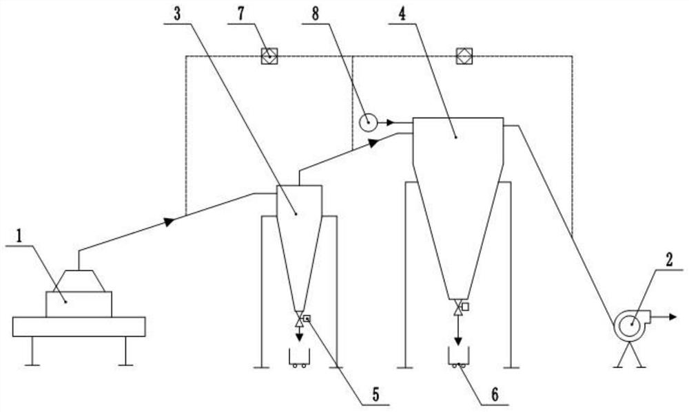
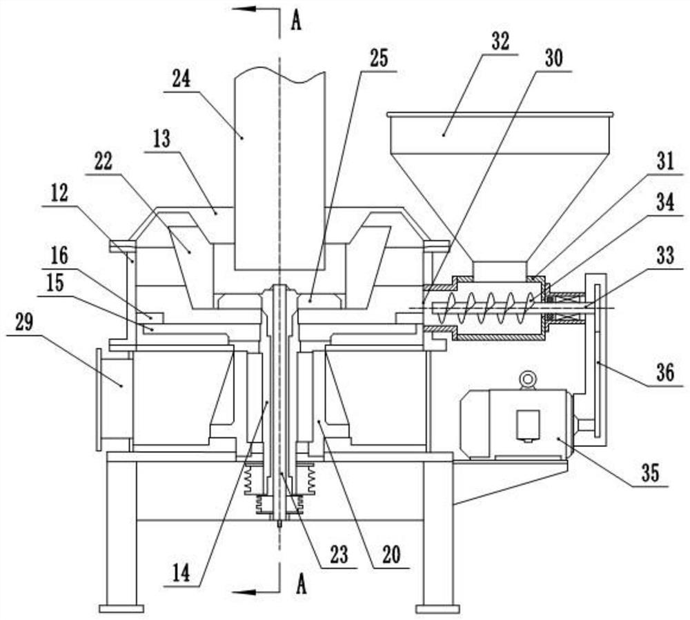
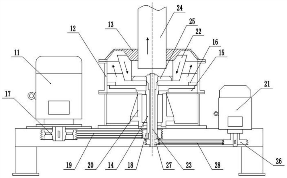
[0037] basically as attached figure 1 , figure 2 and image 3 Shown: a control system for micro-grinding, including a frame, a grinding host 1 and a negative pressure system, wherein the grinding host 1 includes a host motor 11, a host shell 12, a top cover 13, a hollow shaft 14 and a tool rest Assembly, in which the host motor 11 and the host shell 12 are both fixed on the frame, the hollow shaft 14 is rotatably connected in the host shell 12, and the tool holder assembly includes a plurality of sharpeners 15 fixed on the hollow shaft 14 and a fixed The grinding block 16 on the inner wall of the main body casing 12 , wherein the upper surface of the grinding knife 15 is in contact with the lower surface of the grinding block 16 .
[0038] A first belt transmission mechanism is connected between the hollow shaft 14 and the host motor 11, wherein the first belt transmission mechanism includes a first driving pulley 17, a first driven pulley 18 and a first belt 19, and the fi...
Embodiment 2
[0053] The difference from Example 1 is that the combination Figure 4 As shown, the feeding shaft 33 is horizontally connected in the barrel 31 through the bearing and the bearing seat 90, wherein the bearing seat 90 is fixed on the right end of the barrel 31, and the right end of the barrel 31 is provided with a connecting hole 91, and due to the analysis When the main engine is working, there is a large negative pressure wind entering, in order to reduce the loss of lubricating oil in the bearing seat 90 (flow into the material barrel 31 due to the large negative pressure), thereby affecting the quality of the material.
[0054] A plugging cylinder 92 is arranged in the bearing seat 90 close to the connecting hole 91. The plugging cylinder 92 has a porous structure, that is, it is made of porous material. The plugging cylinder 92 is sleeved on the feeding shaft 33, and the plugging cylinder 92 The outer diameter is larger than the diameter of the connecting hole 91, and the...
Embodiment 3
[0056] The difference from Embodiment 1 is that the bottom of the top cover 13 is integrally formed with a conical protrusion, the conical protrusion is large at the top and small at the bottom, and the part of the conical protrusion is located in the air hood 22, so that the conical protrusion is arranged in this way. A guide channel is formed between the raised side wall and the inner wall of the airflow hood 22 , so that the powder can more easily enter the inside of the airflow hood 22 and adhere to the inner wall of the airflow hood 22 under the action of centrifugal force.
PUM
 Abstract
Description
Claims
Application Information
 - R&D
- Intellectual Property
- Life Sciences
- Materials
- Tech Scout
- Unparalleled Data Quality
- Higher Quality Content
- 60% Fewer Hallucinations
Browse by: Latest US Patents, China's latest patents, Technical Efficacy Thesaurus, Application Domain, Technology Topic, Popular Technical Reports.
© 2025 PatSnap. All rights reserved.Legal|Privacy policy|Modern Slavery Act Transparency Statement|Sitemap|About US| Contact US: help@patsnap.com