Three-stage countercurrent evaporation salt separating system for high-salt wastewater and salt separating method thereof

A three-stage countercurrent, high-salt technology, applied in chemical instruments and methods, water/sewage multi-stage treatment, water/sewage treatment, etc., can solve the problem of low discharge temperature and low temperature, which restrict the zero discharge of high-salt wastewater Product recycling and other issues to achieve the effect of improving purity and high discharge temperature

Pending Publication Date: 2021-02-05
JIANGSU TIANYING PLASMA TECH CO LTD +1
View PDF3 Cites 3 Cited by
  • Summary
  • Abstract
  • Description
  • Claims
  • Application Information

AI Technical Summary

Problems solved by technology

The existing technology mostly uses traditional downstream multi-effect evaporation to treat these high-salt wastewater. The wastewater is concentrated step by step to form a slurry. The slurry is centrifuged by a centrifuge to obtain crystallized salt. These slurries have low temperature and difficulty in concentration control. The problem is that it is not conducive to the separation of sodium chloride and potassium chloride; the slurry is centrifuged to separate crystallized salt, which is mostly mixed salt containing sodium chloride and potassium chloride, which is difficult to meet the industrial recycling standard. Seriously restricting the "zero discharge" of high-salt wastewater and the recycling of products
Due to the limitations of many factors such as the current domestic technical level, equipment investment, operating cost and operational stability, high-salt wastewater cannot be effectively separated and crystallized, and the purity of sodium chloride and potassium chloride produced is low. It is difficult to meet the industrial recycling standard; and the traditional evaporative crystallization discharge temperature is low, and the slurry concentration is difficult to control, which is not conducive to the separation of sodium and potassium salts

Method used


Image

  • Three-stage countercurrent evaporation salt separating system for high-salt wastewater and salt separating method thereof

Examples


Embodiment Construction

[0026] In order to elaborate the technical solutions adopted by the present invention to achieve the predetermined technical purpose, the technical solutions in the embodiments of the present invention will be clearly and completely described below with reference to the accompanying drawings in the embodiments of the present invention. Obviously, the described implementation The examples are only some of the embodiments of the present invention, not all of the embodiments, and the technical means or technical features in the embodiments of the present invention can be replaced without creative work. The following will refer to the accompanying drawings in conjunction with Examples are given to illustrate the present invention in detail.

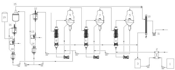
[0027] like figure 1 As shown, a three-stage countercurrent evaporation and salt separation system for high-salt wastewater of the present invention includes a storage tank 1, a preheater 2, a condensed water tank 3, a first heater 4, a first...


PUM


Abstract

The invention discloses a three-stage countercurrent evaporation salt separating system for high-salt wastewater and a salt separating method thereof. The system comprises a storage tank, a preheater,a condensed water tank, a first heater, a first evaporation chamber, a second heater, a second evaporation chamber, a third heater, a third evaporation chamber, a steam condenser, a vacuum pump, a first concentrator, a first centrifugal machine, a first mother liquor tank, a flash chamber, a second concentrator, a second centrifugal machine and a second mother liquor tank, by adopting a process of combining three-stage countercurrent evaporation sodium salt separating and flash evaporation cooling potassium salt separating with opposite flow directions of steam and materials, the discharge temperature is high, the problem that the low discharge temperature is not beneficial to sodium-potassium separating is solved, and the problem of coprecipitation of potassium chloride and sodium chloride is solved by controlling the concentration of discharged potassium chloride.

Description

technical field [0001] The invention relates to a salt separation system and a salt separation method, in particular to a three-stage countercurrent evaporation salt separation system and a salt separation method for high-salt waste water, belonging to the field of industrial waste water recycling. Background technique [0002] In industrial production, wastewater often containing sodium chloride and potassium chloride, such as waste incineration power plants, landfills, plasma fly ash melting plants, etc., will produce a large amount of high-salt wastewater in the actual production process. The salt wastewater is pretreated, dosing, coagulation, sedimentation, filtration and other processes to remove impurities such as heavy metals and SS in the wastewater, and the remaining solution contains sodium chloride, potassium chloride and other components. In the prior art, traditional co-current multi-effect evaporation is often used to treat these high-salt wastewater. The waste...

Claims


Application Information

Patent Timeline
Patent Type & Authority Applications(China)
IPC IPC(8): C02F9/10C01D3/04C01D3/14
CPCC02F9/00C01D3/04C01D3/14C02F1/048C02F1/38C02F1/06C01P2006/80
Inventor 尤润泽江中央孙钟华曹德标李要建
Owner JIANGSU TIANYING PLASMA TECH CO LTD
Why Eureka
Try Eureka