A processing method for thin-walled complex cavity

A processing method and cavity technology are applied in the field of workpiece processing to achieve the effects of easy quality control and increased brazing area

Active Publication Date: 2021-09-28
XIAN YUANHANG VACUUM BRAZING TECH
View PDF0 Cites 0 Cited by
  • Summary
  • Abstract
  • Description
  • Claims
  • Application Information

AI Technical Summary

Problems solved by technology

[0004] The invention provides a processing method for a thin-walled complex cavity, which solves the problem that the thin-walled complex cavity workpiece cannot be processed by conventional methods such as precision casting and argon arc welding.

Method used


Image

  • A processing method for thin-walled complex cavity
  • A processing method for thin-walled complex cavity
  • A processing method for thin-walled complex cavity

Examples


Embodiment 1

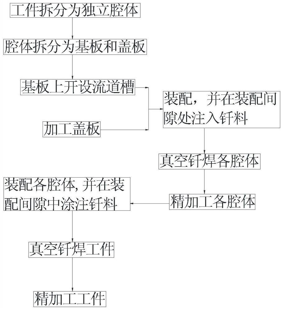
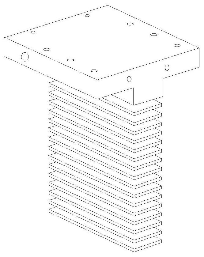
[0037] a kind of like figure 2 The processing method of the thin-walled complex cavity shown, such as figure 1 shown, including the following steps:

[0038] S1. If figure 2 As shown, the workpiece is split into multiple layers according to the internal flow channel structure, so that each layer becomes an independent cavity;

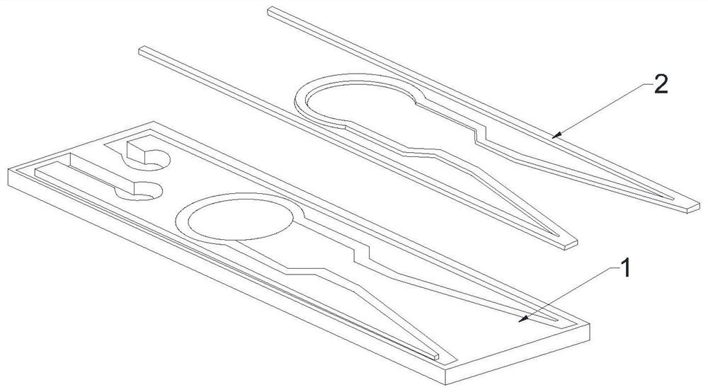
[0039] S2. If image 3 As shown, each cavity is divided into a base plate and a cover plate, a runner groove is opened on the base plate, and a cover plate matching the runner groove is processed; Figure 4 As shown, the joint form of the runner groove and the cover plate is set as a lap joint. The bottom of the runner groove is opened as a square runner, and the top is opened as a square overlap groove with a size larger than the square runner. The size of the cover plate is the same as that of the square overlap. The grooves are matched; and chamfers are processed at the top corners of the cover;

[0040] The runner groove and the cover plate o...

Embodiment 2

[0060] On the basis of embodiment 1, the procedure of the vacuum brazing of each independent cavity is:

[0061] Vacuuming: cold vacuum degree 0.03Pa, working vacuum degree 0.05Pa;

[0062] Heating and heating: heating to 440°C at a rate of 150°C / h and holding for 30 minutes; heating to 900°C at a rate of 300°C / h and holding for 200 minutes; heating to 1050°C at a rate of 410°C / h;

[0063] Vacuum brazing: Brazing at 1050°C for 20 minutes;

[0064] Cooling and cooling: vacuum cooling to 600°C with the furnace, filling high-purity nitrogen into the furnace, turning on the fan to stir, and the pressure reaches 8×10 4 After Pa, start the fan and cool down to 70°C for release;

[0065] Under the action of capillary force, the solder can fully infiltrate, dissolve, diffuse and weld with the solid metal of the workpiece.

[0066] The conditions of each independent cavity are:

[0067] The condition of the pressure test is to test under 4MPa water pressure for 25 minutes to ensure...

Embodiment 3

[0070] The vacuum brazing procedure of the workpiece is:

[0071] Vacuuming: cold vacuum degree 0.04Pa, working vacuum degree 0.03Pa;

[0072] Heating and heating: heating at a rate of 150 °C / h to 400 °C and holding for 50 minutes; heating at a rate of 350 °C / h to 880 °C and holding for 100 min; heating at a rate of 490 °C / h to 1050 °C;

[0073] Vacuum brazing: Brazing at 1050°C for 30 minutes;

[0074] Cooling and cooling: vacuum cooling to 550°C with the furnace, filling the furnace with high-purity nitrogen, and the pressure reaches 9×10 4 After Pa, start the fan and cool to 60°C;

[0075] After the workpiece is brazed, the pressure test is carried out on the workpiece; the condition of the pressure test is to test under 4MPa water pressure for 20 minutes to ensure that the flow channel has no cavity, blockage, leakage and deformation;

[0076] The pressure test conditions for each independent cavity and workpiece are:

[0077] The condition of the pressure test is to t...


PUM


Abstract

The invention relates to the technical field of workpiece processing, and discloses a processing method for a thin-walled complex cavity, which includes the following steps: S1. Splitting the workpiece into multiple layers according to the internal flow channel structure, so that each layer becomes an independent cavity; S2 .Split each cavity into a base plate and a cover plate, set a runner groove on the base plate, process a cover plate matching the runner groove, and process chamfers at the top corners of the cover plate; S3. Clean and polish each The cover plate and the base plate of each cavity, respectively assemble the cover plate and the base plate, and inject solder into the fiber seam along the chamfer of the cover plate; S4. Put each cavity into a vacuum furnace for vacuum brazing; S5. Finishing The surface of each cavity; S6. Clean and polish each cavity, and assemble it into a workpiece, and inject solder into the weld; S7. Put the workpiece into a vacuum furnace for vacuum brazing; S8. Finish the workpiece after brazing . The method of vacuum brazing processes thin-walled complex cavity workpieces, realizes the simultaneous welding of multiple individual complex cavities and the overall welding of the workpiece, and meets the size and precision requirements of the workpiece.

Description

technical field [0001] The invention relates to the technical field of workpiece processing, in particular to a processing method for a thin-walled complex cavity. Background technique [0002] Thin-walled complex cavity workpieces cannot be processed by general processing methods due to their fine and complex internal structures. Available processing methods include 3D printing, but the cost of 3D printing is relatively high, and the precision cannot be guaranteed within 0.05-0.1mm . [0003] The base of the scramjet engine is mainly composed of two independent cavities, the working air flow cavity and the cooling water cavity. The cooling water cavity is composed of 16 layers of water-cooling channels connected in parallel. The outer wall of the seat is distributed to cool the working airflow wall. The water-cooling flow channel is a 2mm*2mm rectangular flow channel with a wall thickness of 1mm. The contour of the mating surface on the outer surface of the base is require...

Claims


Application Information

Patent Timeline
Patent Type & Authority Patents(China)
IPC IPC(8): B23P15/00B23K1/008
CPCB23K1/008B23P15/00
Inventor 任军刘洋
Owner XIAN YUANHANG VACUUM BRAZING TECH
Why Eureka
Try Eureka