Inclined U-shaped chiral structure and preparation method thereof

A chiral structure, U-shaped technology, applied in the field of tilted U-shaped chiral structure and its preparation, can solve the problems of complex three-dimensional chiral nanostructure, high input cost, complicated process, etc., achieve excellent field enhancement effect, reduce Loss, simple structure effect

Inactive Publication Date: 2021-02-09
中山科立特光电科技有限公司
View PDF0 Cites 1 Cited by
  • Summary
  • Abstract
  • Description
  • Claims
  • Application Information

AI Technical Summary

Problems solved by technology

[0005] The purpose of the present invention is to provide a tilted U-shaped chiral structure and its preparation method for the deficiencies in the above-mentioned prior art, so as to solve the complex three-dimensional chiral nanostructure in the prior art and produce chirality. The mechanism of the signal is complex, and its preparation often requires multiple electron beam etching, the process is complicated, and the input cost is high

Method used


Image

  • Inclined U-shaped chiral structure and preparation method thereof
  • Inclined U-shaped chiral structure and preparation method thereof
  • Inclined U-shaped chiral structure and preparation method thereof

Examples


Embodiment 1

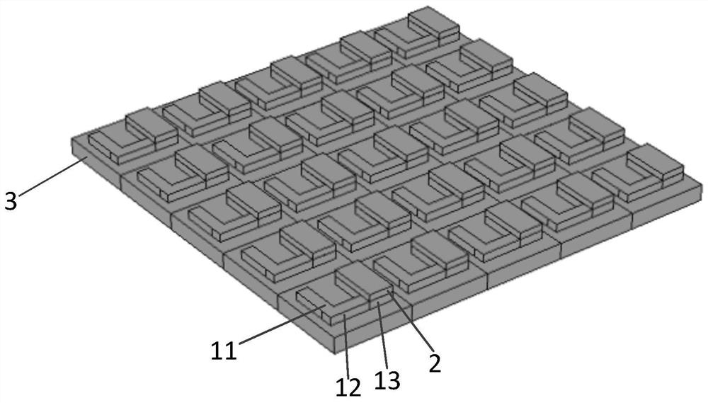
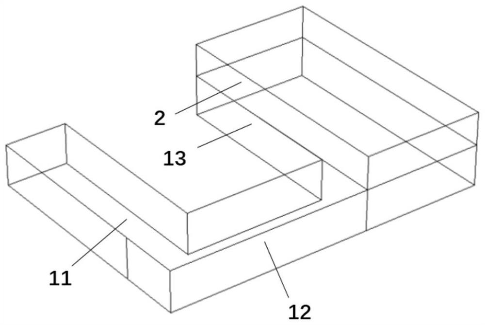
[0039] The present application provides a tilted U-shaped chiral structure, which includes: a substrate 3 and a plurality of chiral units periodically arranged on the substrate 3, each chiral unit includes a first rectangular bar 11, a second rectangular bar 12, a third Rectangular strip 13 and raised portion 2, the two ends of the second rectangular strip 12 are respectively connected with the first rectangular strip 11 and the third rectangular strip 13, the first rectangular strip 11 and the third rectangular strip 13 are parallel to each other, and the first rectangular strip The strip 11 and the third rectangular strip 13 are all perpendicular to the second rectangular strip 12, the first rectangular strip 11, the second rectangular strip 12 and the third rectangular strip 13 form a "U"-shaped structure, and the protrusion 2 is arranged on the third rectangular strip. The strip 13 is away from the side of the base 3 , and the projections of the raised portion 2 and the thi...

Embodiment 2

[0047] Optionally, the width of the first rectangular strip 11 is equal to the width of the second rectangular strip 12, and the thicknesses of the first rectangular strip 11, the second rectangular strip 12, and the third rectangular strip 13 perpendicular to the direction of the base 3 are equal.

[0048] Optionally, the width of the third rectangular strip 13 is greater than the widths of the first rectangular strip 11 and the second rectangular strip 12 , and the lengths of the first rectangular strip 11 , the second rectangular strip 12 and the third rectangular strip 13 increase sequentially.

[0049] Optionally, the first rectangular strip 11 and the second rectangular strip 12 have a width of 150 nanometers, the third rectangular strip 13 has a width of 300 nanometers, the first rectangular strip 11 has a length of 450 nanometers, and the second rectangular strip 12 has a width of 300 nanometers. The length is 500 nanometers, the length of the third rectangular strip 13...

Embodiment 3

[0054] Based on Embodiment 1, this embodiment of the present application provides another inclined U-shaped structure. It is basically the same as Embodiment 1, the only difference is that the inclined U-shaped structure is composed of two different materials.

[0055] Optionally, the material of the pad portion is silicon, and the material of the protruding portion 2 is a noble metal material. That is to say, the materials of the first rectangular strip 11 , the second rectangular strip 12 and the third rectangular strip 13 are all silicon, and the material of the protruding portion 2 is noble metal material.

[0056] Optionally, the precious metal material is any one of gold, silver and copper. Preferably, the structure is made of silver. The price is cheaper than gold, which can save experimental costs.

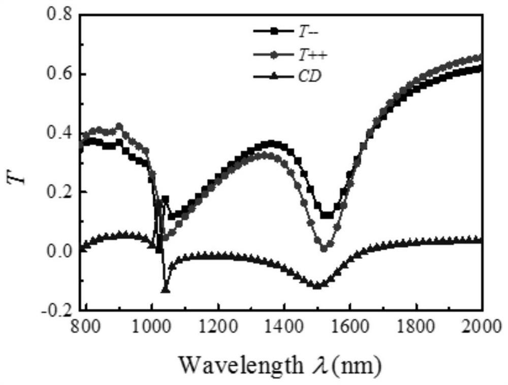
[0057] For the convenience of explanation, the calculation and simulation experiment of the tilted U-shaped chiral structure is carried out here by using the three-dime...


PUM

PropertyMeasurementUnit
Thicknessaaaaaaaaaa
Thicknessaaaaaaaaaa

Abstract

The invention relates to an inclined U-shaped chiral structure and a preparation method thereof, in particular to the field of micro-nano photonics structures. The structure comprises a substrate anda plurality of chiral units periodically arranged on the substrate, each chiral unit comprises a first rectangular strip, a second rectangular strip, a third rectangular strip and a protruding part, the first rectangular strip, the second rectangular strip and the third rectangular strip form a U-shaped structure, and the protruding part is arranged on the side, away from the substrate, of the third rectangular strip. Under the excitation of incident circular polarized light, a combined dipole is formed on the protruding part and the third rectangular strip, and due to the fact that the dipoleis not parallel to the oscillation path of the dipole on the first rectangular strip and the oscillation path of the dipole on the second rectangular strip, the phase difference between structures iscaused, the phase difference between the dipoles of the structure can be changed by flexibly controlling the thickness and the shape of the protruding part, so that a flexible and controllable chiralsignal is generated, and a new mechanism is provided for the generation of the chiral signal.

Description

technical field [0001] The invention relates to the field of micro-nano photonics structures, in particular to a tilted U-shaped chiral structure and a preparation method thereof. Background technique [0002] The word chirality is derived from Greek and means the symmetry of structure, which has important meaning in many disciplines. An object is said to be "chiral" if it is different from its mirror image, and its mirror image cannot be superimposed on the original object, just as the left and right hands are mirror images of each other and cannot be superimposed. Chirality is the basic characteristic of life process, and most of the organic molecules that make up living organisms are chiral molecules. [0003] The chiral signals of chiral molecules in nature are generally very weak. In recent years, researchers have discovered that surface plasmons generated by chiral metal nanostructures can be used to enhance chiral signals. Because the helical structure can generate...

Claims


Application Information

Patent Timeline
IPC IPC(8): G02B5/00G03F7/00
CPCG02B5/008G03F7/00
Inventor 不公告发明人
Owner 中山科立特光电科技有限公司
Why Eureka
Try Eureka