Discretized region scanning subarray-level sparse optimization method and system

An area scanning and sparse optimization technology, applied in the field of array antenna design, can solve the problems that the minimum distance is difficult to meet the distance limit conditions, the ultra-large-scale array does not have engineering realization, and the effective point group is low, so as to save processing time and improve the obtained results. The probability of the optimal solution, the effect of increasing the effective ratio

Active Publication Date: 2021-02-09
CHINA ELECTRONIC TECH GRP CORP NO 38 RES INST
View PDF9 Cites 2 Cited by
  • Summary
  • Abstract
  • Description
  • Claims
  • Application Information

AI Technical Summary

Problems solved by technology

[0004] In the existing position point generation scheme, all array elements can be randomly arranged in any position in the target area, and the minimum distance between any two points is judged. When the distance between any two points meets the distance constraint condition, the group of position points is valid point group; but when the limit distance is large or the number of array elements is large, the minimum distance between two points in the generated position point group is difficult to meet the distance restriction condition, resulting in most of the generated point groups being invalid p

Method used


Image

  • Discretized region scanning subarray-level sparse optimization method and system
  • Discretized region scanning subarray-level sparse optimization method and system
  • Discretized region scanning subarray-level sparse optimization method and system

Examples


Embodiment 1

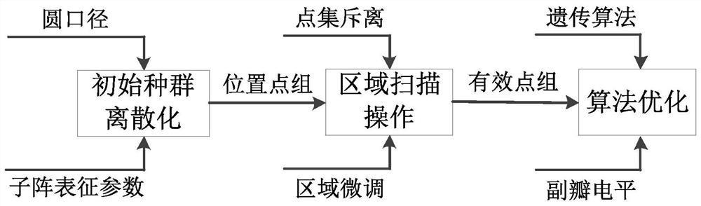
[0066] This embodiment provides a subarray-level sparse optimization method for discretized area scanning, and finally obtains the subarray distribution of the optimal sparse array and the array pattern at the time of the lowest sidelobe.

[0067] Such as figure 1 as shown, figure 1 It is the flow chart of the method for discretized area scanning subarray-level sparse optimization in this embodiment. The array antenna to be optimized has a circular aperture and a radius of R. The array arrangement adopts the form of subarrays. The minimum distance between subarrays that do not overlap is D. 0 , the number of sub-arrays is N 0 .

[0068] The method includes the following steps:

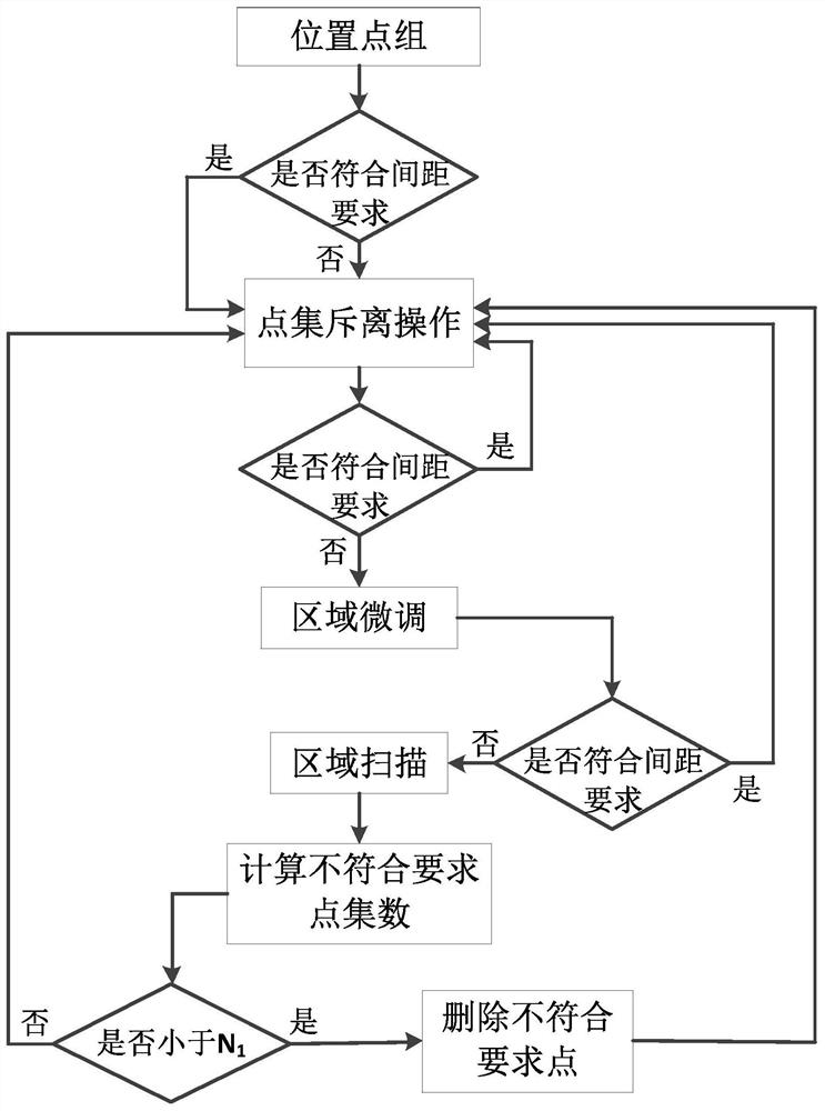
[0069] S1: Initial population discretization

[0070] A discrete position point group is randomly generated, and the position point group contains the initial position information of all subarrays.

[0071] Specific steps are as follows:

[0072] (11) Establish a coordinate system on the plane w...

Embodiment 2

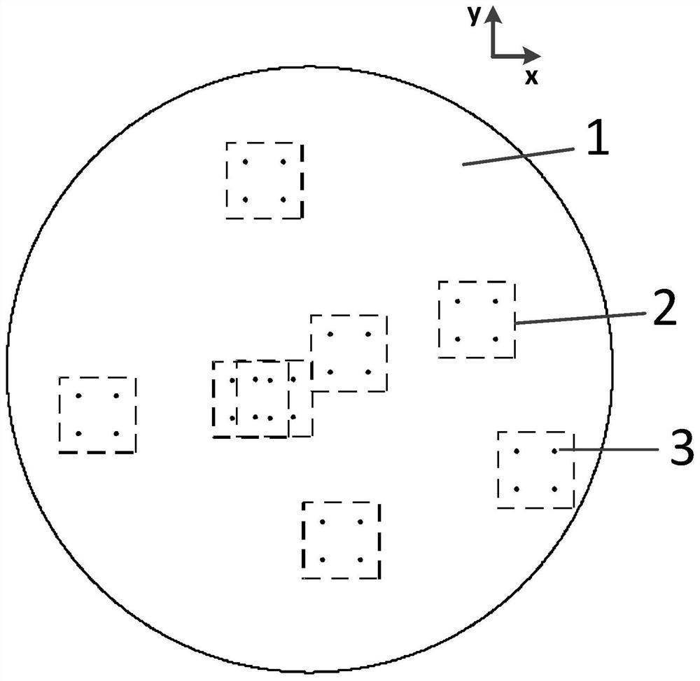
[0093] In this embodiment, the performance of the circular aperture array antenna pattern is optimized, and the frequency point to be optimized is 5 GHz. Set the x-axis and y-axis as image 3 shown. The radius of the circular aperture to be optimized is 200mm, the size of the sub-array is 2*2, and the cell spacing in the sub-array is 30mm; the number of sub-arrays to be optimized is 8, and the minimum spacing between the sub-arrays is 70mm. The sub-array radius fine-tuning interval is 0.2mm, and the number of fine-tuning points is 50; the angle fine-tuning interval is 0.2°, and the number of fine-tuning points is 200. The subarray radius scanning interval is 0.5mm, and the number of scanning points is 200; the angular scanning interval is 0.5°, and the number of scanning points is 720. The direction pattern to be optimized is the normal φ=0° cut plane, and the target side lobe is -20dB. During the optimization process, the parameters to be optimized consist of the position ...

Embodiment 3

[0097] In this embodiment, the performance of the pattern of the large-sized circular aperture array antenna is optimized, and the frequency point to be optimized is 3.5 GHz. Set the x-axis and y-axis as Image 6 shown. The radius of the circular aperture to be optimized is 3m, the size of the sub-array is 4*4, and the cell spacing in the sub-array is 42mm; the number of sub-arrays to be optimized is 50, and the minimum spacing between the sub-arrays is 245mm. The sub-array radius fine-tuning interval is 0.5mm, and the number of fine-tuning points is 400; the angle fine-tuning interval is 0.2°, and the number of fine-tuning points is 200. The sub-array radius scanning interval is 1mm, and the number of scanning points is 2000; the angular scanning interval is 0.5°, and the number of scanning points is 720. The direction pattern to be optimized is the normal φ=0° cut plane, and the target side lobe is -20dB. During the optimization process, the parameters to be optimized are...


PUM


Abstract

The invention discloses a discretized region scanning subarray-level sparse optimization method and system, and belongs to the technical field of array antenna design, and the method comprises the following steps: S1, discretizing an initial population; s2, carrying out region scanning processing; and s3, optimization processing. When the method and the system are applied to sub-array-level sparseoptimization of a large-scale circular aperture antenna, under the condition that the sub-array spacing meets the spacing requirement, the optimization time is greatly reduced, the sidelobe level isreduced, a new way is provided for rapidly solving effective position arrangement of array elements under the specific array element spacing limitation condition, the diversity of a solution set in the optimization process is improved, the probability of finding the optimal solution is improved, and local convergence of the optimization algorithm is effectively avoided; and when the designed arrayantenna is applied to a large-scale radar system, the radar has the advantages of long operating distance, high resolution, low cost, light weight, high engineering realizability and the like, and isworthy of popularization and application.

Description

technical field [0001] The invention relates to the field of array antenna design, in particular to a method and system for discretized area scanning sub-array-level sparse optimization. Background technique [0002] With the development of radar detection and reconnaissance technology, the demand for radar working distance is gradually increasing. The antenna is responsible for the transmission and reception of radar signals, and the demand for its gain makes the aperture area of ​​the antenna array larger and larger. In the antenna array design, a large number of antenna elements and T / R components are required when large-scale radars are arranged at equal intervals, and the production cost is high. In order to reduce the number of antenna elements and channels, sparse array design has been developed rapidly. Genetic algorithm, particle swarm algorithm, and simulated annealing algorithm can find the optimal solution through iteration and evolution. In order to avoid fall...

Claims


Application Information

Patent Timeline
IPC IPC(8): G06F30/27
CPCG06F30/27Y02D30/70
Inventor 朱庆超方佳徐龙陶蕾张小林金谋平
Owner CHINA ELECTRONIC TECH GRP CORP NO 38 RES INST
Why Eureka
Try Eureka