Building emission reduction reactor based on photoelectrocatalysis system

A photoelectric catalysis and reactor technology, applied in chemical instruments and methods, gas treatment, chemical/physical processes, etc., can solve problems such as inability to generate economic benefits, difficulty in achieving zero emissions, promotion restrictions, etc., and achieve poor economic efficiency , control building emissions, and alleviate the effect of the greenhouse effect

Pending Publication Date: 2021-02-12
TIANJIN UNIV
View PDF0 Cites 0 Cited by
  • Summary
  • Abstract
  • Description
  • Claims
  • Application Information

AI Technical Summary

Problems solved by technology

TiO 2 The research on the application of photocatalytic materials mainly focuses on the four directions of purification of polluting gases, environmental sterilization, self-cleaning and anti-fog of building surfaces, and enhancement of heat transfer performance of air-conditioning refrigeration, and most of them focus on photocatalytic coatings, self-cleaning glass, functional Ceramics, photocatalytic concrete and other composite building materials exist, but there is no effective and feasible technical route for photocatalytic technology in mitigating the greenhouse effect
[0003] In addition, the existing green building technology also has many limitations, for example, the emission reduction effect is limited, and it is difficult to achieve the goal of zero emission; moreover, the design and construction are relatively complicated, the cost is high and cannot produce economic benefits, and the promotion is limited to a certain extent
These problems are not conducive to the green development of the construction industry

Method used


Image

  • Building emission reduction reactor based on photoelectrocatalysis system
  • Building emission reduction reactor based on photoelectrocatalysis system
  • Building emission reduction reactor based on photoelectrocatalysis system

Examples


Embodiment Construction

[0020] The present invention will be further elaborated below according to specific embodiments.

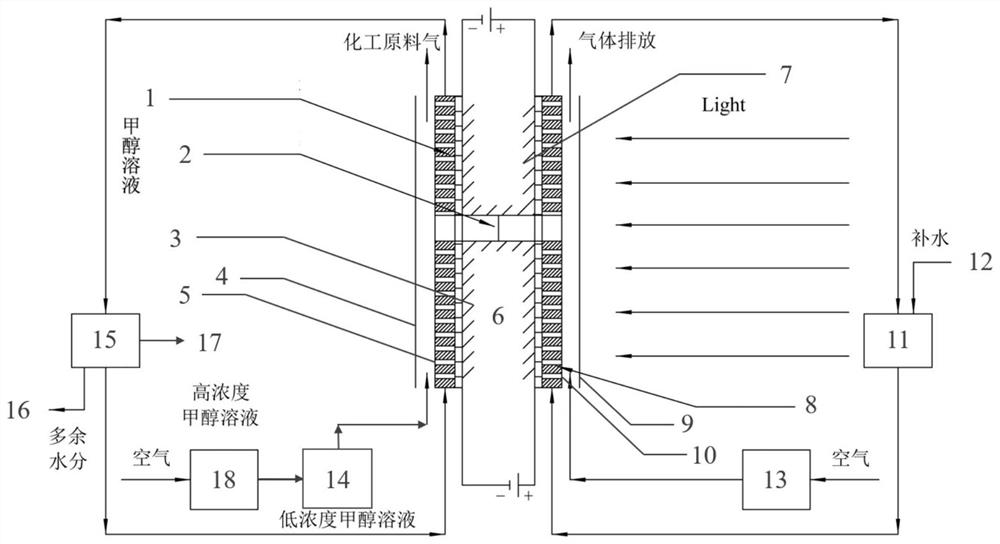
[0021] Such as Figure 1-4 The shown building emission reduction reactor based on the photoelectric catalytic system includes a photoanode system, a dark cathode system and a DC power supply. The photoanode system is arranged on the outer surface 7 of the building, and the dark cathode system is arranged on the inner surface 3 of the building.

[0022] The photoanode system includes a phototropic photoanode 8, a first selective transmission film 10, a light-transmitting protective layer 9, a water pump 11, a first air pump 13, an anode solution pool, an acid solution pipeline and a first gas pipeline.

[0023] The first selective permeable film is arranged on the outside of the phototropic photoanode, the light-transmitting protective layer is arranged on the outside of the first selective permeable film, and the anode solution pool is arranged on the outer surface of the buildin...


PUM


Abstract

A building emission reduction reactor based on a photoelectrocatalysis system comprises a photo-anode system, a dark cathode system and a direct-current power source, the photo-anode system is arranged on the outer surface of a building, and the dark cathode system is arranged on the inner surface of the building. An idle resource, namely a building wall body with a huge surface area, and renewable solar energy are fully utilized, and carbon dioxide is absorbed and oxygen is released by virtue of a photoelectrocatalysis reaction, so that the building emission is effectively controlled, and thegreenization level of a building is improved.

Description

technical field [0001] The invention relates to the technical field of green buildings, more specifically, to a building emission reduction reactor based on a photoelectric catalytic system. Background technique [0002] Among all photocatalytic materials, TiO 2 It is one of the green environmental protection materials with the most development prospects, and it is also the most deeply researched photocatalytic material in the field of green buildings at home and abroad. TiO 2 The research on the application of photocatalytic materials mainly focuses on the four directions of purification of polluting gases, environmental sterilization, self-cleaning and anti-fog of building surfaces, and enhancement of heat transfer performance of air-conditioning refrigeration, and most of them focus on photocatalytic coatings, self-cleaning glass, functional Ceramics, photocatalytic concrete and other composite building materials exist, but there is no effective and feasible technical r...

Claims


Application Information

Patent Timeline
Patent Type & Authority Applications(China)
IPC IPC(8): B01J19/08B01J19/12B01D53/86B01D53/62
CPCB01D53/62B01D53/86B01D2255/20707B01D2257/504B01J19/08B01J19/12B01J19/127Y02A50/20
Inventor 白纪韬李韦伊郑鑫蕊张思淼徐杰
Owner TIANJIN UNIV
Why Eureka
Try Eureka