A copper mesh and copper foil welding method

A welding method and copper mesh technology, applied in the field of metal welding, can solve the problems of affecting the appearance, unstable long-term operation, large floor space, etc., and achieve the effect of reducing the fluctuation of focal depth and achieving the effect of reliability and strength

Active Publication Date: 2022-04-12
SHENZHEN JIXIANGYUN TECH CO LTD
View PDF7 Cites 0 Cited by
  • Summary
  • Abstract
  • Description
  • Claims
  • Application Information

AI Technical Summary

Problems solved by technology

Disadvantages: Ultrasonic friction welding is double-sided contact welding, which requires strong stress, which will directly dent the workpiece on both sides and seriously affect the appearance; there is a layer of plastic film on the copper mesh, which will be affected by heat during ultrasonic friction welding. Damage to the plastic film; welding speed is slow, welding a 1mm 2 It takes 1-4 seconds for the area, and it takes 5-10 seconds for clamping. It is difficult to realize the automatic welding of copper mesh and copper foil
Disadvantages: The outlet point is relatively large, and the outlet point is easy to break, resulting in false welding and inconsistent welding; there is a layer of plastic film on the copper mesh, and the plastic film will be damaged due to heat influence during resistance touch welding welding, and the resistance touch welding welding points are in contact Small area, high pressure, easy to deform copper foil
But the disadvantage is: the YAG welding process is suitable for welding a single point, or a line formed by a single point, the copper mesh copper foil welding point is only 2mm, this welding method is not suitable for dense line welding; the welding area is about 2mm 2 When the welding strength is low, it is difficult to pull Li Xiao, and there are traces on the back of the copper foil; YAG collection occupies a large area (the more the whole system needs 3-5m 2 ), high energy consumption (about 10KW), consumables (xenon lamp, optical fiber, protective lens, filter element, water, etc.), welding spots will become weaker with the attenuation of xenon lamp, resulting in inconsistent solder joints and unstable long-term operation; welding efficiency Higher than traditional welding, but the efficiency is only 20-50% of this process

Method used


Image

  • A copper mesh and copper foil welding method

Examples


Embodiment Construction

[0026] The following will clearly and completely describe the technical solutions in the embodiments of the present invention with reference to the accompanying drawings in the embodiments of the present invention. Obviously, the described embodiments are only some, not all, embodiments of the present invention. Based on the embodiments of the present invention, all other embodiments obtained by persons of ordinary skill in the art without making creative efforts belong to the protection scope of the present invention.

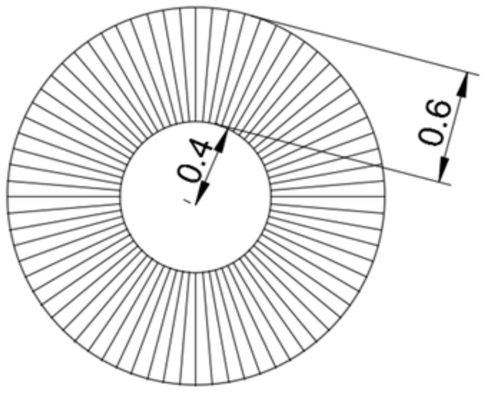
[0027] see figure 1 , in an embodiment of the present invention, a copper mesh and copper foil welding method, comprising the following steps:

[0028] (1) Laser type selection: 50-150W Fiber laser is used as the welding light source, and the laser adopts MOPA, Q-switched, QCW quasi-continuous pulse type;

[0029] (2) Configuration of laser optics: Use galvanometers suitable for spot diameters of 10, 12, 14, 16, 18, 20, 25, and 30mm as welding beam movement c...


PUM


Abstract

The invention discloses a copper mesh and copper foil welding method, comprising the following steps: (1) laser type selection: a 50-150W Fiber laser is used as a welding light source, and the laser adopts MOPA, Q-switching, and QCW quasi-continuous pulse types; 2) Configuration of laser optics: Use galvanometers suitable for spot diameters of 10, 12, 14, 16, 18, 20, 25, and 30 mm as welding beam movement components; use quartz or polymer field mirrors as focusing optical components; The specification of the mirror is any one of F=160, 163, and 170mm; (3) Placement and compression of copper mesh and copper foil; (4) Determine the laser parameter settings; (5) The pattern formed by laser scanning by the galvanometer Track and process method: the invention realizes the reliability and strength of solder joints around the copper mesh.

Description

technical field [0001] The invention relates to the technical field of metal welding, in particular to a copper mesh and copper foil welding method. Background technique [0002] In the prior art, the copper mesh and the copper foil are usually welded by ultrasonic friction welding, resistance butt welding, YAG laser spot welding and the like. [0003] Ultrasonic friction welding: The working principle is to transmit ultrasonic energy to the welding area through the upper weldment. Since the welding area, that is, the interface between the two welds, has a large acoustic resistance, local high temperature will be generated. And because the heat of the contact surface cannot be dissipated in time, it gathers in the welding area, causing the contact surface of the two solders to melt rapidly, and after a certain pressure is added, it is fused into one. When the ultrasonic wave stops working, let the pressure continue for a few seconds to make it solidify and form, thus formin...

Claims


Application Information

Patent Timeline
Patent Type & Authority Patents(China)
IPC IPC(8): B23K26/21
CPCB23K26/21
Inventor 陈燕张雪松刘梅军黄再福
Owner SHENZHEN JIXIANGYUN TECH CO LTD
Why Eureka
Try Eureka