Leaked fuel gas return-flow structure for engine

An engine and gas technology, applied in the direction of engine components, machines/engines, mechanical equipment, etc., can solve the problems of reduced engine lubrication performance, increased engine size, easy occurrence of sand sintering, etc., to achieve improved sealing performance, improved lubrication performance, The effect of preventing sand sintering

An engine and gas technology, applied in the direction of engine components, machines/engines, mechanical equipment, etc., can solve the problems of reduced engine lubrication performance, increased engine size, easy occurrence of sand sintering, etc., to achieve improved sealing performance, improved lubrication performance, The effect of preventing sand sintering

CN1123675CInactive Publication Date: 2003-10-08SUZUKI MOTOR CO LTD

Image

  • Leaked fuel gas return-flow structure for engine
  • Leaked fuel gas return-flow structure for engine
  • Leaked fuel gas return-flow structure for engine

Examples


Embodiment Construction

[0050] Embodiments of the present invention will be described in detail below in conjunction with the accompanying drawings.

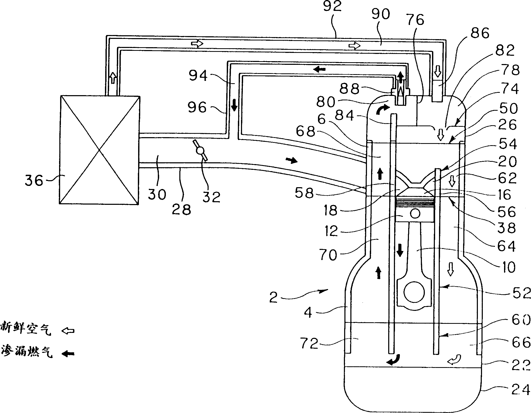
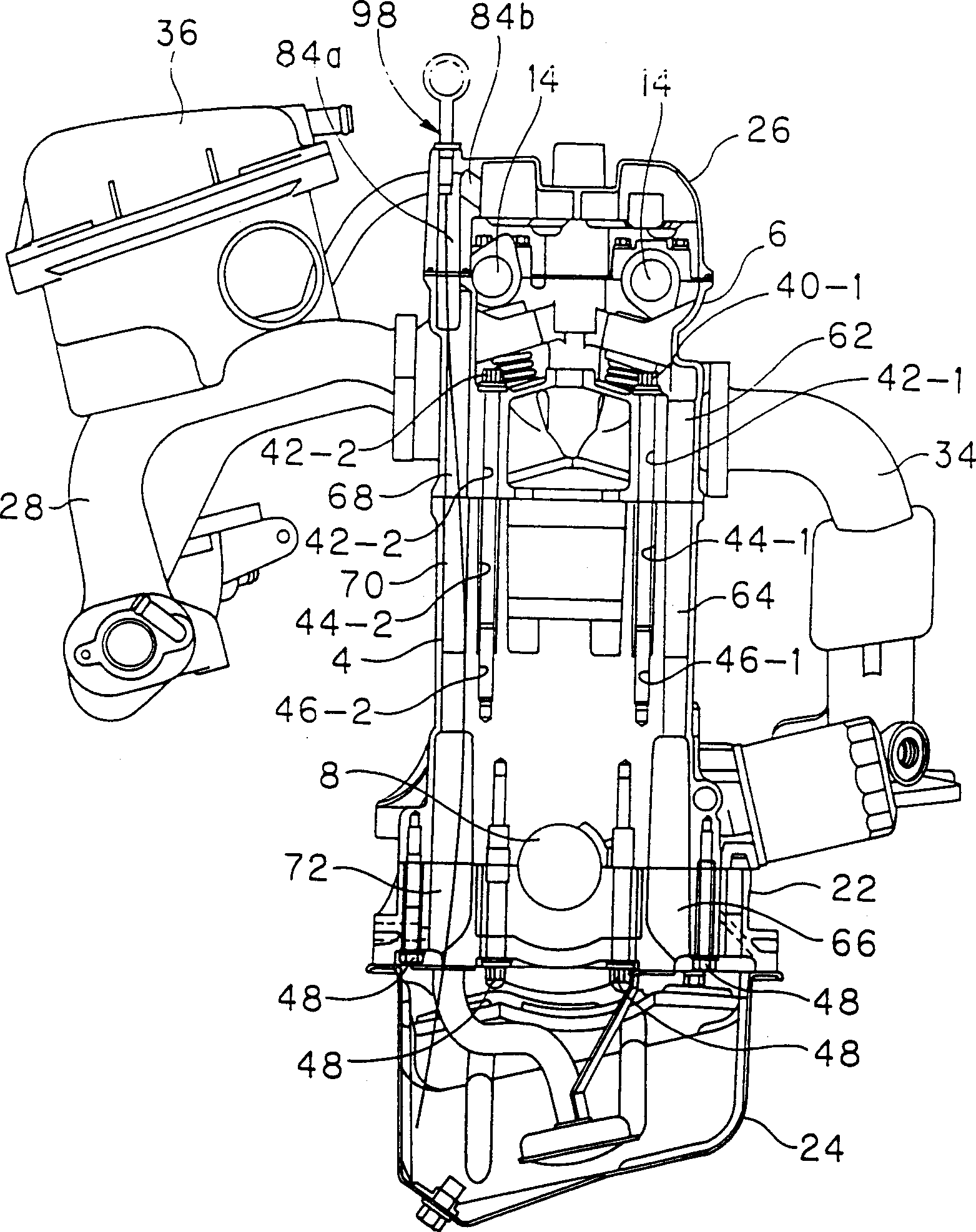
[0051] figure 1 and 2 A first embodiment is shown. exist figure 1 and 2 Among them, 2 is the engine; 4 is the cylinder block; 6 is the cylinder head; 8 is the crankshaft; 10 is the connecting rod; 12 is the piston; 14 is the camshaft; 16 is the combustion chamber; 18 is the air inlet; 20 is the air outlet; 22 is a crankcase; 24 is an oil tank; 26 is a cylinder front cover; 28 is an intake manifold; 30 is an intake passage; 32 is a throttle valve; 34 is an outlet manifold; 36 is an air cleaner.

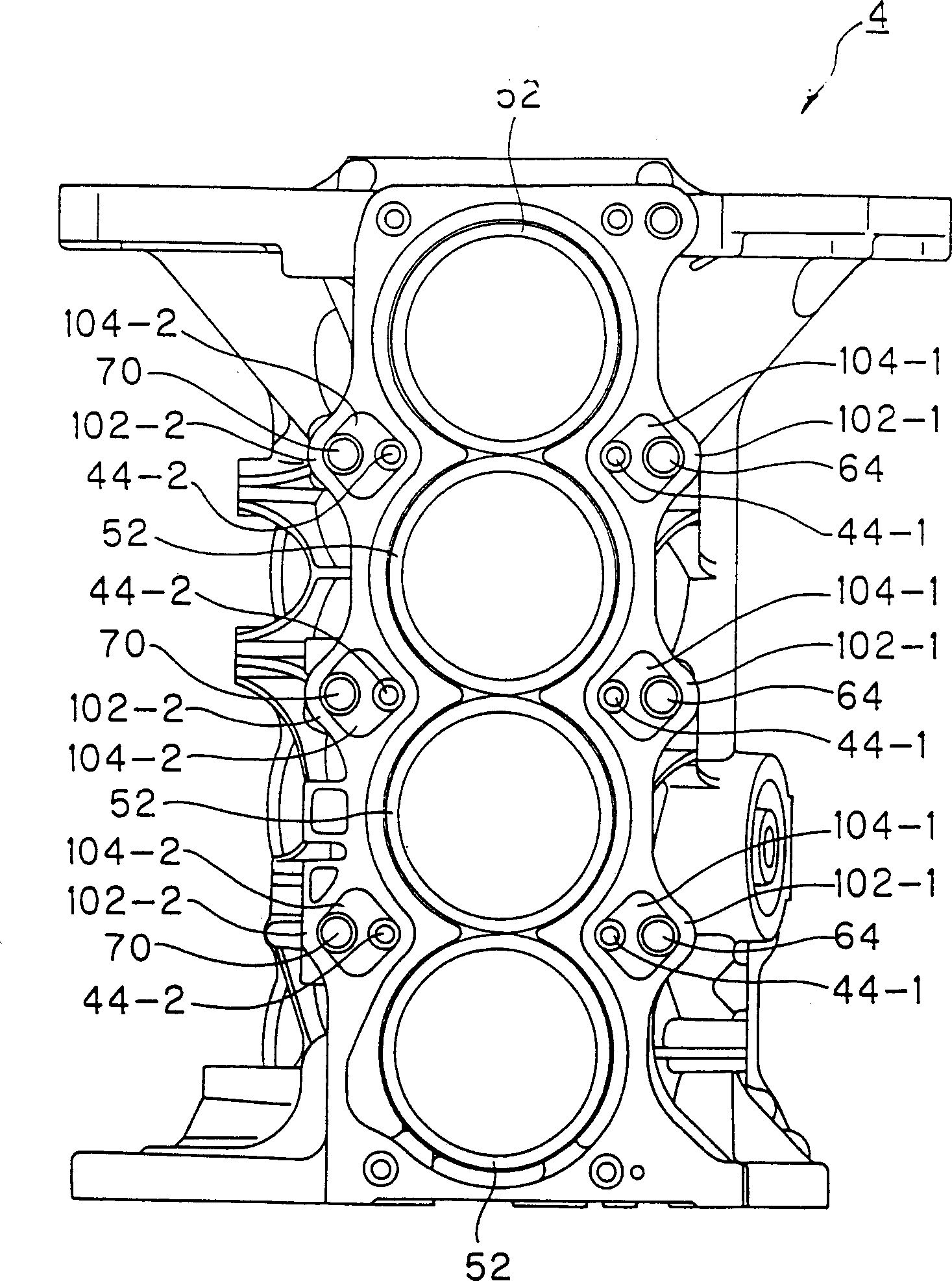
[0052] The cylinder head 6 is fastened on the top surface of the cylinder block 4 via a cylinder head gasket 38 with a plurality of first and second cylinder head mounting bolts 40-1 and 40-2. These bolts 40-1 and 40-2 pass through the first and second cylinder head side bolt holes 42-1 and 42-2 in the cylinder head 6, and then pass through the cylinder ...


PUM


Abstract

A blowby gas-returning structure for an engine which is adapted to provide smooth returning of a blowby gas, and to provide a light-weight or compact engine. The blowby gas-returning structure is provided with passage-forming object or wall in order to continue blowby gas passages without interruption. Further, the cylinder block may be provided with void space sections which share space with the blowby gas passages and the cylinder head-mounting bolt holes. In addition, the blowby gas passage in the cylinder head may be disposed offset substantially midway along the length thereof.

Description

technical field [0001] This application is a divisional application of the patent application with the application number 97120232.X, the application date being October 29, 1997, and the title being "leakage gas return structure of engine". [0002] The invention relates to a leaking gas return structure of an engine, in particular to a leaking gas return structure of an engine which can smoothly return the leaking gas. Background technique [0003] In the engine, gas leaks from the combustion chamber into the crankcase through the gap between the piston and the cylinder liner. The main component of the leakage gas is the unburned gas containing a large amount of hydrocarbon (HC), which needs to flow back into the combustion chamber for reburning. For this purpose, a blowby gas recirculation system is used, in which, as is known, the flow rate control valve (PCV valve) is driven with the intake manifold pressure of the intake system as the loading state of the engine, so th...

Claims


Application Information

Patent Timeline
08 Oct 2003
Publication
CN1123675C
IPC
F01M13/00; F01M13/02; F02B75/18; F02B75/20; F02F1/00; F02F7/00
CPC
F02F7/006; F01M13/022; F02B2075/1816; F02B2275/18; F01M13/028; F02B75/20
Inventors
笠原智