

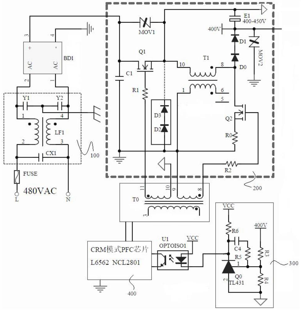
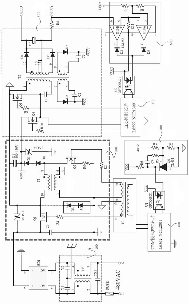
Floating buck-boost PFC circuit and LED driving power supply
A buck-boost, floating technology, applied in the field of power electronics, can solve the problems of high cost, large product volume, high cost, etc., and achieve the effect of low product cost, simple circuit and high conversion efficiency
- Summary
- Abstract
- Description
- Claims
- Application Information
AI Technical Summary
Problems solved by technology
Method used
Image

Examples
Embodiment Construction
[0021] In order to facilitate the understanding of the present invention, the present invention will be described more fully below with reference to the associated drawings. A preferred embodiment of the invention is shown in the drawings. However, the present invention can be embodied in many different forms and is not limited to the embodiments described herein. Rather, these embodiments are provided so that the disclosure of the present invention will be thorough and complete.
[0022] Unless otherwise defined, all technical and scientific terms used herein have the same meaning as commonly understood by one of ordinary skill in the technical field of the invention. The terms used herein in the description of the present invention are for the purpose of describing specific embodiments only, and are not intended to limit the present invention.
[0023] In addition, the terms "first" and "second" are used for descriptive purposes only, and cannot be interpreted as indicatin...
PUM
 Abstract
Description
Claims
Application Information