
Medical instrument tibia bone fracture plate for orthopedic surgery

A surgical operation and medical device technology, applied in the field of medical devices, can solve the problems affecting the firmness of the bone plate, unfavorable fracture healing of patients, and affecting the growth of bone tissue, achieving good stability and fixation effects, reducing stress shielding effects, The effect of promoting fracture healing

Inactive Publication Date: 2021-02-19
陈博
View PDF8 Cites 0 Cited by
  • Summary
  • Abstract
  • Description
  • Claims
  • Application Information

AI Technical Summary

Problems solved by technology

At present, the internal fixation materials used clinically are mainly titanium alloy materials. This material has the advantages of excellent corrosion resistance and mechanical properties, but its biocompatibility is poor, the price is expensive, and its density and elasticity are quite different from natural bone. , easy to cause stress shielding phenomenon, affect the growth of bone tissue and prolong the healing time
Moreover, the patient is prone to fracture of the bone plate due to the action of external force during the treatment, thus failing
[0004] In the prior art, the bone plate for the tibia generally only has screw holes with a fixed diameter and angle. For different fracture sites, using the same pattern of screws for fixation often affects the firmness of the bone plate fixation, and poor fixation may lead to The emergence of iatrogenic fractures is not conducive to the healing of patients' fractures

Method used


Image

  • Medical instrument tibia bone fracture plate for orthopedic surgery
  • Medical instrument tibia bone fracture plate for orthopedic surgery
  • Medical instrument tibia bone fracture plate for orthopedic surgery

Examples


Embodiment Construction

[0025] In order to make the technical means, creative features, goals and effects achieved by the present invention easy to understand, the present invention will be further described below in conjunction with specific embodiments.

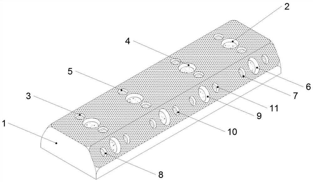
[0026] Such as Figure 1-7 As shown, the present invention is a tibial bone plate, a medical device for orthopedic surgery, comprising a bone plate main body 1, the two ends of the front of the bone plate main body 1 are fixed and penetrated with main fixing holes 2 at the front end, and the two front ends of the bone plate main body 1 are fixed. The two sides of the main fixing hole 2 at the front end are provided with auxiliary fixing holes 3 at the front end, and the middle of the front middle of the bone plate main body 1 is symmetrically provided with the main fixing holes 4 at the front middle, and the front middle of the bone plate main body 1 is located at the front The two sides of the main fixing hole 4 in the middle part are symmetrical...


PUM

PropertyMeasurementUnit
The inside diameter ofaaaaaaaaaa
Thicknessaaaaaaaaaa

Abstract

The invention discloses a medical instrument tibia bone fracture plate for an orthopedic surgery. The medical instrument tibia bone fracture plate comprises a bone fracture plate body, front face endmain fixing holes are fixedly formed in the two ends of the front face of the bone fracture plate body in a penetrating mode, front face end auxiliary fixing holes are formed in the positions, locatedon the two sides of the front face end main fixing holes, of the two ends of the front face of the bone fracture plate body in a penetrating mode, front face middle main fixing holes are symmetrically formed in the middle of the front face of the bone fracture plate body in a penetrating mode, front face middle auxiliary fixing holes are symmetrically formed in the positions, on the two sides ofthe front face middle main fixing holes, of the middle of the front face of the bone fracture plate body in a penetrating mode, side face end main fixing holes are formed in the two ends of the side face of the bone fracture plate body in a penetrating mode, and side face middle main fixing holes are symmetrically formed in the middle of the side face of the bone fracture plate body in a penetrating mode. The medical instrument tibia bone fracture plate has the advantages that the structure is simple and reasonable, the design is novel, and the higher tibia fixing firmness is realized in the tibia bone fracture aspect.

Description

technical field [0001] The invention relates to the technical field of medical instruments, in particular to a tibial bone plate, a medical instrument for orthopedic surgery. Background technique [0002] The tibia is one of the two bones of the lower leg and is located on the inner side of the lower leg. It plays an important role in supporting body weight and is the main load-bearing bone in the lower leg. It can be divided into one body and two ends. The upper end is usually called the proximal end, and the lower end is usually called the distal end. The distal end fracture is a multiple fracture, and the fracture of the backbone between the two ends is a tibial body fracture. Happens less often, but still happens. [0003] Tibial fractures are a type of multiple fractures, accounting for about 1 / 4 of all fractures in the whole body. At present, the internal fixation materials used clinically are mainly titanium alloy materials. This material has the advantages of excel...

Claims


Application Information

Patent Timeline
IPC IPC(8): A61B17/80A61L31/02A61L31/14A61L31/16
CPCA61B17/8057A61B17/8061A61B2017/00831A61L31/022A61L31/028A61L31/14A61L31/148A61L31/16A61L2300/10A61L2300/404A61L2300/408A61L2300/602
Inventor 陈博石海飞蒋帅
Owner 陈博
Learn More