Mechanical drying device for biomass particle production

A biomass particle and drying device technology, applied in drying, drying machine, drying gas arrangement, etc., can solve problems such as not easy to form, easy to break, unable to maintain shape, etc., to ensure factory quality and uniform output , the effect of complete shape

Inactive Publication Date: 2021-02-19
湖南中泉环保能源科技有限公司
View PDF6 Cites 4 Cited by
  • Summary
  • Abstract
  • Description
  • Claims
  • Application Information

AI Technical Summary

Problems solved by technology

[0003] At present, the storage of biomass straw pellets needs to be dried first. After drying, the water content of the straw is about 12%. The storage is convenient and the cycle is long. It needs to be dried during the production process. For straw biomass fuel, it is directly dried at high temperature. , It is enough to reduce the water content strongly. Since the straw contains moisture inside, the straw particles will contain a lot of water during the manufacturing process, the temperature is as high as 80-90°C, the structure is relatively loose and easy to break, and the straw particles are easy to assemble into Agglomerates, resulting in insufficient follow-up drying, which makes the drying of straw particles incomplete. The existing drying device is equipped with a stirring device inside to stir and dry the straw particles, which will make the agglomerated straw particles dry When it is broken, it will be broken by the stirring device, so that the structure of the straw particles is incomplete, the size of the straw particles is inconsistent, the shape of the production cannot be maintained, and it is not easy to shape, which affects the subsequent quality of the factory.

Method used


Image

  • Mechanical drying device for biomass particle production
  • Mechanical drying device for biomass particle production
  • Mechanical drying device for biomass particle production

Examples


Embodiment Construction

[0018] The following will clearly and completely describe the technical solutions in the embodiments of the present invention with reference to the accompanying drawings in the embodiments of the present invention. Obviously, the described embodiments are only some, not all, embodiments of the present invention. Based on the embodiments of the present invention, all other embodiments obtained by persons of ordinary skill in the art without making creative efforts belong to the protection scope of the present invention.

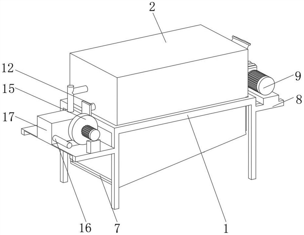
[0019] see Figure 1-5 , the present invention provides a technical solution: a mechanical drying device for biomass particle production, including a support frame 1, and the top of the support frame 1 is provided with a drying and screening device that can evenly dry the agglomerated straw particles Device 2, the drying device 6 is placed on the place that needs to be dried.

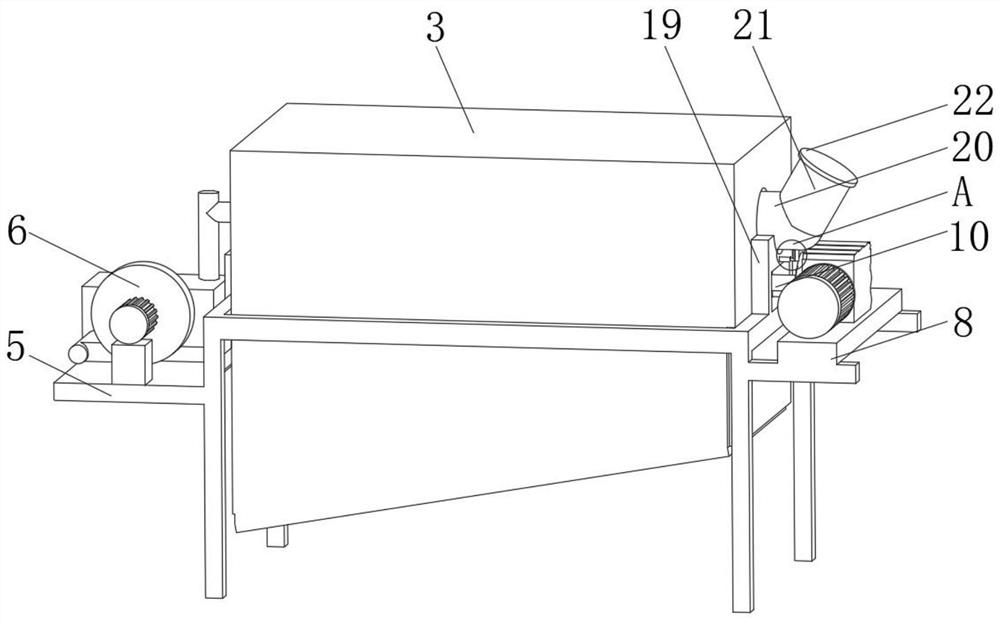
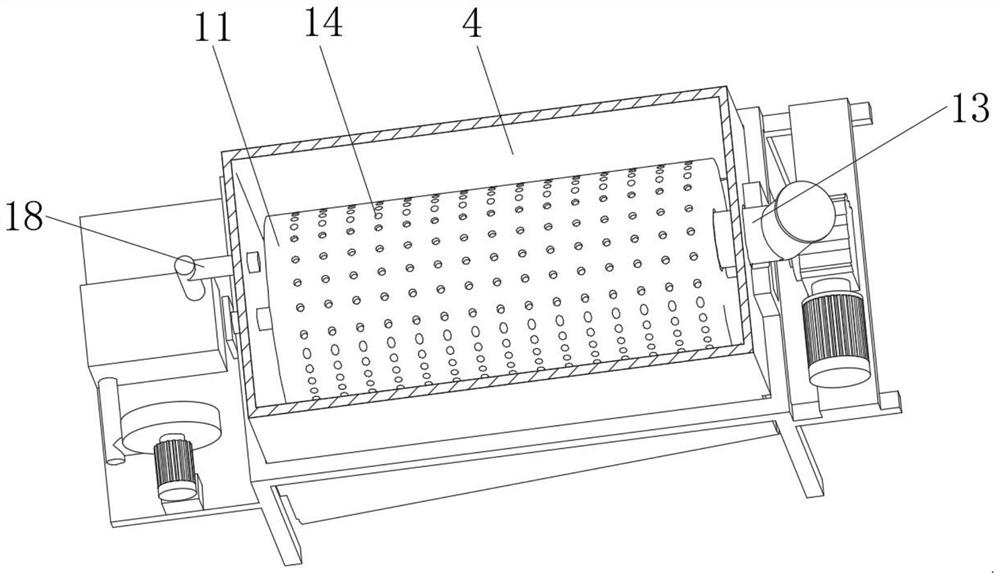
[0020] The drying and screening device 2 includes an outer drying cylinder 3 posit...


PUM


Abstract

The invention discloses a mechanical drying device for biomass particle production. The mechanical drying device comprises a supporting frame, wherein a drying and screening device capable of uniformly drying straw particles gathered into a cluster is arranged at the top of the supporting frame; the drying and screening device comprises an outer drying cylinder located at the top of the supportingframe; a feeding and screening device is arranged inside the outer drying cylinder; a supporting plate is arranged on the outer side of one end of the supporting frame; a drying device is arranged atthe top of the supporting plate; the bottom of the outer drying cylinder is an inclined surface; and a discharging port is formed in the inclined angle position of one end of the outer drying cylinder. According to the drying device for biomass straw particle production, the drying and screening device is additionally arranged on an original drying device so that the biomass straw particles can be uniformly dried, the dried straw particles can be screened, the shape after processing can be kept, and the outgoing quality of the straw particles is guaranteed; and the straw particles can be screened while being uniformly dried, and the shape integrity of the straw particles is guaranteed.

Description

technical field [0001] The invention relates to the technical field of biomass particle production, in particular to a mechanical drying device for biomass particle production. Background technique [0002] According to the definition of the International Energy Agency (IEA), biomass refers to various organisms formed through photosynthesis, including all animals, plants and microorganisms. Biomass energy is the energy form of solar energy stored in biomass in the form of chemical energy. It has always been one of the important energy sources for human survival, and it is the fourth largest energy source after coal, oil, and natural gas. plays an important role in the system. Straw pellet fuel is a kind of fuel that is pressed and formed by corn stalks, wheat straw, rice straw and other crops through a straw pellet machine at high temperature. [0003] At present, the storage of biomass straw pellets needs to be dried first. After drying, the water content of the straw is ...

Claims


Application Information

Patent Timeline
Patent Type & Authority Applications(China)
IPC IPC(8): F26B11/04F26B21/00F26B25/00F26B25/02F26B25/12F26B25/16
CPCF26B11/04F26B21/001F26B25/002F26B25/02F26B25/12F26B25/16
Inventor 刘伟二
Owner 湖南中泉环保能源科技有限公司
Why Eureka
Try Eureka