Recycling process and recycling system for wastewater and waste residues in concrete mixing plant

A technology for concrete waste and concrete, applied in mixers, multi-stage water/sewage treatment, water/sludge/sewage treatment, etc. problems, to achieve the effect of resource utilization, pollution reduction, and reduction in the use of clean water

Active Publication Date: 2021-02-23
中建西部建设北方有限公司
View PDF11 Cites 2 Cited by
  • Summary
  • Abstract
  • Description
  • Claims
  • Application Information

AI Technical Summary

Problems solved by technology

However, the problem with this method is that when the concrete production volume is small, only a limited amount of waste slurry water can be consumed, and a large amount of remaining waste slurry water cannot be completely consumed and disposed of, resulting in a great waste of resources and environmental pollution

Method used


Image

  • Recycling process and recycling system for wastewater and waste residues in concrete mixing plant
  • Recycling process and recycling system for wastewater and waste residues in concrete mixing plant
  • Recycling process and recycling system for wastewater and waste residues in concrete mixing plant

Examples


Embodiment 1

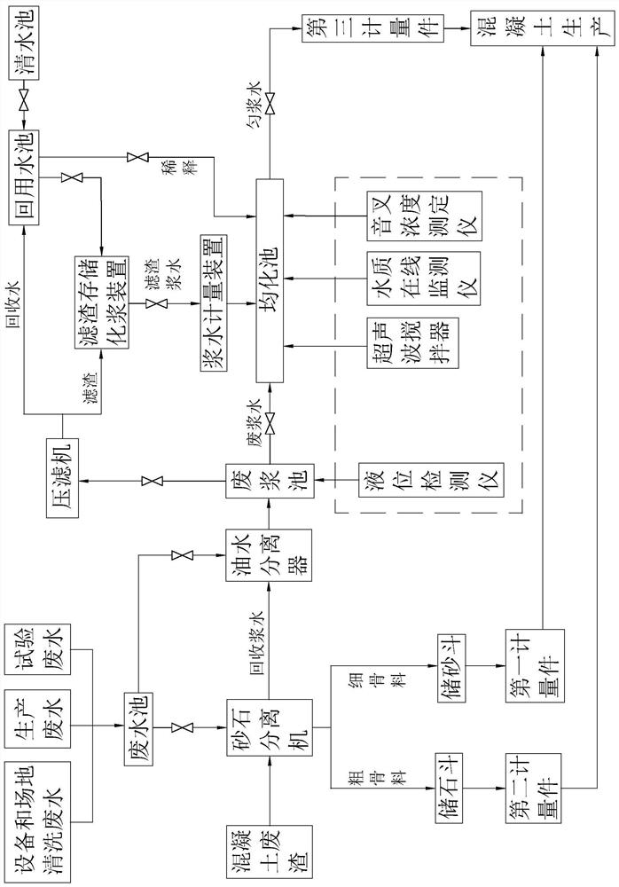
[0049] refer to figure 1 The wastewater and residue reuse system of the concrete mixing plant includes a sand and gravel separation unit, a waste slurry water collection and monitoring unit, a waste slurry water control unit, a reuse unit, and a control unit; the sand and gravel separation unit includes a liquid collection tank and a sand and gravel separator; The slurry water collection and monitoring unit includes an oil-water separator, a waste slurry tank, a homogenization tank, a stirring device, and a slurry water monitoring device; the waste slurry water control unit includes a liquid level monitoring device, a filter press, a recovery pool, a filter residue storage slurry device, and Slurry water metering device; the recycling unit includes a sand storage bucket, a stone storage bucket and a metering device. The metering device includes a first metering piece matched with the sand storage bucket, a second metering piece matched with the stone storage bucket, and a homog...

Embodiment 2

[0067] This embodiment discloses a process for reusing waste water and slag from a concrete mixing plant, which differs from the process for reusing waste water and slag in a concrete mixing plant disclosed in Example 1 in that:

[0068] S23. Use an online water quality monitor to monitor the pH value, sulfate ion concentration, and chloride ion concentration of the homogenate water, and use a tuning fork concentration detector to monitor the concentration of the homogenate water;

[0069] When it is detected that the monitored value of the homogenized water is higher than the standard value, the control unit gets feedback, controls the recovery water tank to supply water to the homogenized tank, and dilutes the homogenized water in the homogenized tank until the monitored value of the homogenized water is exceeded. Adjust to below the standard value;

[0070] During the peak production period of the concrete mixing plant, when the accumulation rate of the filter residue is gr...


PUM


Abstract

The invention relates to the field of building material recycling, in particular to a recycling process and system for wastewater and waste residues in a concrete mixing plant. The recycling process comprises the following steps: separating concrete waste residues to obtain coarse aggregate, fine aggregate and recycled slurry water, and subjecting the obtained coarse aggregate and fine aggregate to concrete production; removing oil from the obtained recycled slurry water and and the wastewater of the concrete mixing plant, and carrying out collecting and storing to obtain waste slurry water; stirring the obtained waste slurry water to obtain homogenate water, and carrying out filter pressing treatment on the waste slurry water which cannot be recycled in time to obtain filter residues andrecycled water; and carrying out concentration monitoring and pH value monitoring on the obtained homogenate water, and applying the homogenate water with qualified monitoring values to concrete production. The recycling system comprises a gravel separation unit, a waste slurry water collecting and monitoring unit, a waste slurry water control unit, a recycling unit and a control unit. The processand the system have the effect of fully recycling the wastewater and the waste residues of the concrete mixing plant.

Description

technical field [0001] The application relates to the field of recycling of building materials, in particular to a recycling process and a recycling system for waste water and residue of a concrete mixing plant. Background technique [0002] With the wide application of commercial concrete, concrete mixing stations produce a large amount of waste water and waste while producing commercial concrete. The discharge of these wastes mainly comes from the waste water and waste slurry produced by cleaning the mixer truck, the mixer main engine, and washing the production site, as well as the surplus of concrete factory monitoring and sampling, surplus and scrap concrete caused by irresistible factors. [0003] In order to reduce the impact of waste slurry water discharge on the environment, the main disposal method of concrete enterprises at present is to use sand and gravel separation equipment to separate sand and gravel for recycling, and then add a certain amount of clean water...

Claims


Application Information

Patent Timeline
Patent Type & Authority Applications(China)
IPC IPC(8): B01D36/00C02F9/02B01F13/10
CPCB01D36/00C02F1/40C02F1/001B01F33/831
Inventor 张凯峰童小根王军罗作球孟刚张磊邰炜胡宇博王佳敏王国峰
Owner 中建西部建设北方有限公司
Why Eureka
Try Eureka